Table of Contents
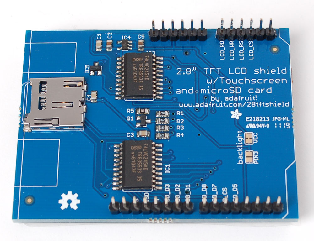
2.8" TFT touch screen shield
Spice up your Arduino project with a beautiful large touchscreen display shield with built in microSD card connection. This TFT display is big (2.8" diagonal) bright (4 white-LED backlight) and colorful (18-bit 262,000 different shades)! 240x320 pixels with individual pixel control. It has way more resolution than a black and white 128x64 display. As a bonus, this display has a resistive touchscreen attached to it already, so you can detect finger presses anywhere on the screen.
The shield is fully assembled, tested and ready to go. No wiring, no soldering! Simply plug it in and load up our library - you'll have it running in under 10 minutes!
This display shield has a controller built into it with RAM buffering, so that almost no work is done by the microcontroller. The shield does require a lot of pins: 12 lines total for the display, 13 total if you use the microSD card
Of course, we wouldn't just leave you with a datasheet and a "good luck!" - we've written a full open source graphics library that can draw pixels, lines, rectangles, circles and text . We also have a touch screen library that detects x, y and z (pressure) and example code to demonstrate all of it. The code is written for Arduino but can be easily ported to your favorite microcontroller!
Pick one up today at the Adafruit Shop!
Specifications:
- 2.8" diagonal LCD TFT display
- 240x320 resolution, 18-bit (262,000) color
- ILI9325 (datasheet) or ILI9328 (datasheet) controller with built in video RAM buffer
- 8 bit digital interface, plus 4 control lines
- Uses digital pins 5-13 and analog 0-3. That means you can use digital pins 2, 3 and analog 4 and 5. Pin 12 is available if not using the microSD
- Works with any Arduino '328 or Mega
- 5V compatible! Use with 3.3V or 5V logic
- Onboard 3.3V @ 300mA LDO regulator
- 4 white LED backlight. On by default but you can connect the transistor to a digital pin for backlight control
- 4-wire resistive touchscreen
Frequently Asked Questions
- I was just looking through the datasheet and I notice there is an SPI interface available. Why do you use the parallel interface? SPI would be better fewer pins!
Even though the display driver supports SPI, we have not found any displays that could use it - the pins are simply not available on the display connector. Also, SPI would be incredibly, frustratingly slow for such a large screen. If you need an SPI display, check out many of our other offerings, nearly all support SPI-like protocols!
- All the pins are used! How can I connect anything to the Arduino??
We suggest using a protoshield (with stacking headers) or a proto-screwshield to access the unused pins (2, 3, and analog 4 and 5). You can connect various i2c sensors or analog sensors to analog 4&5. You can also connect an i2c port expander to get more I/O pins. If you desperately need more pins, and you're careful, you can use the 8 datapins while the TFT isn't being written to - they are high-z and unused as long as the WR and RD pins are high
Easy to use - just snap on!

Because the TFT is exactly the same size as an Arduino, we preassemble the shield in the factory. To use, simply place it onto your Arduino. No wiring, no soldering!
LCD test
We have a library with example code ready to go for use with these TFTs. The library is not incredibly fast and optimized but its a good start and can easily be ported to other micrcontrollers. However, we'll assume you're using an Arduino
Visit our github repository and click on the Downloads button in the top right corner to download a zip of the library and examples. Uncompress the folder and rename it TFTLCD make sure that inside that folder is the cpp and .h files. Then copy it to your arduinosketchfolder/libraries folder. See our tutorial for more details.
You will also need to get the GFX graphics core and click on the Downloads button in the top right corner to download a zip of the library and examples. Uncompress the folder and rename it Adafruit_GFX make sure that inside that folder is the cpp and .h files. Then copy it to your arduinosketchfolder/libraries folder.
For this shield, there is one more step! Open up the TFTLCD.h file in the libraries folder and uncomment the line at the top that says:
//comment or uncomment the next line for special pinout!
#define USE_ADAFRUIT_SHIELD_PINOUT
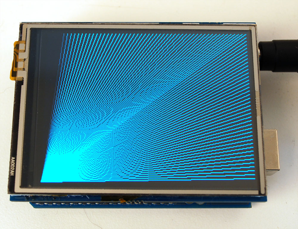
Restart the Arduino software. You should see a new example folder called TFTLCD and inside, an example called graphicstest. Upload that sketch to your Arduino. You should see a collection of graphical tests draw out on the TFT
Adafruit GFX Library
The TFT LCD library is based off of the Adaftui GFX graphics core library. GFX has many ready to go functions that should help you start out with your project. Its not exhaustive and we'll try to update it if we find a really useful function. Right now it supports pixels, lines, rectangles, circles, round-rects, triangles and printing text as well as rotation.
Check out the GFX tutorial for detailed information about what is supported and how to use it!
Touchscreen Paint example
The LCD has a 2.8" 4-wire resistive touch screen glued onto it. You can use this for detecing finger-presses, stylus', etc. You'll need 4 pins to talk to the touch panel but we reuse some of the pins for the TFT LCD! This is because the resistance of the panel is high enough that it doesn't interfere with the digital input/output and we can query the panel in between TFT accesses, when the pins are not being used.
Visit our github repository and click on the Downloads button in the top right corner to download a zip of the library and examples. Uncompress the folder and rename it TouchScreen make sure that inside that folder is the cpp and .h files. Then copy it to your arduinosketchfolder/libraries folder. See our tutorial for more details.
We connect the 4 pins as follows:
- Y+ is connected to Analog 1
- Y- is connected to Digital 7
- X+ is connected to Digital 6
- X- is connected to Analog 2
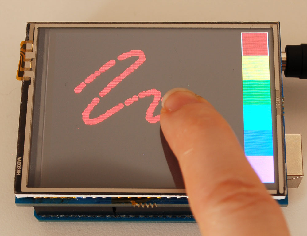
Now start up the tftpaint_shield example in the TFTLCD library. The right hand side will have 'color boxes' you can press to select which color you want to draw with. If you press the area to the left where the screen ends, it will erase the screen.
The touch screen is made of a thin glass sheet, and its very fragile - a small crack or break will make the entire touch screen unusable. Don't drop or roughly handle the TFT and be especially careful of the corners and edges.
When pressing on the touchscreen, sometimes people can use the tip of their fingers, or a fingernail. If you don't find the touchscreen responds well to your fingers, you can use a rounded stylus which will certainly work. Do not press harder and harder until the screen cracks!
Bitmaps from microSD card
There is a built in microSD card slot into the shield, and we can use that to load bitmap images! You will need a microSD card formatted FAT16 or FAT32 (they almost always are by default)
The SD card socket shares pins with the TFT, so many of the 'default' example sketches for the SD card will not work without following the initialization steps in this sketch. Before assuming that the TFT shield is broken because the default SD examples wont work, run this BMP drawing sketch. If you need to use the microSD card holder look carefully at the example sketch to see the steps to initialize the card and TFT in order
You'll also need to download our SD library modifyied to allow faster reads (these changes will be added to arduino v23) but for now you can download the new library here . Download the library by clicking the Downloads button and uncompressing the folder. Replace the files in your ArduinoIDE/libraries/SD folder and restart the IDE.
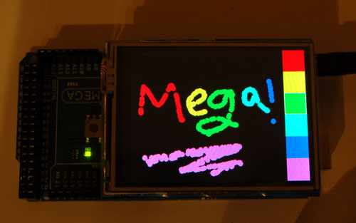
FOR MEGA ARDUINOS edit the SD/utility/Sd2Card.h file after installing and uncomment the line that says #define MEGA_SOFT_SPI 1 to allow the Mega to use the same pinout for SD cards as the Classic Arduinos
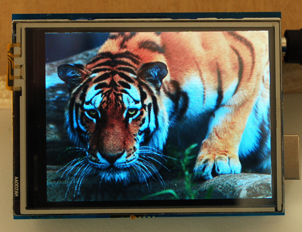
Download this tiger bitmap and save it to the microsd card! (Image by Shane Gorski)
Start up the IDE and select the tftbmp_shield sketch. Upload it to your Arduino to see the tiger!
To make new bitmaps, make sure they are less than 240 by 320 pixels and save them in 24-bit BMP format! They must be in 24-bit format, even if they are not 24-bit color as that is the easiest format for the Arduino. You can rotate images using the setRotation() procedure
Controlling the backlight
By default, we assume you'll want the backlight on all the time. However, you may want to PWM control or otherwise turn off the LED backlight to save power. You can do this with a simple hack. On the back, look for the two backlight jumpers. Cut the trace between the VCC jumper using a sharp knife and then solder the jumper labeled Pin 3. Then you can use Digital 3 to control the backlight
Downloads
For files on github, download by clicking the Downloads button in the top right only!
