Table of Contents
LED full color (RGB) Pixels!
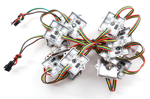
RGB Pixels are digitally-controllable lights you can set to any color, or animate. Each metal pixel contains 4 RGB LEDs and a controller chip soldered to a PCB. The pixel is then 'flooded' with epoxy to make it waterproof. These are fairly large pixels but they have a lot of nice mounting options, such as two metal flanges on the side and a 0.15"/4mm diameter hole in the middle so you can screw them directly onto a surface. They're typically used to make outdoor signs. Compared to our other LED dots, these are much bigger and much brighter, good for larger scale installations.
Basic stats
- 36mm square waterproof pixels
- Approximately 3 inches (75mm) apart on 4-pin strand
- 12 Volts DC, 120 milliamps max per pixel (all LEDs on, full white)
- WS2801 LED driver chip provides 24-bit color: Datasheet
- 2-pin SPI-like protocol — easy for Arduino and other microcontrollers
You can pick up RGB pixels in strands of 20 from the Adafruit shop.
Here is a basic video showing some 36mm pixels running a test pattern:
Project Ideas
These pixels could be used for stuff like…
LED coffee tables (this one is 'hand made' but you could skip the wiring/drivers part and just use a long strand of our LED pixels now)
Signs or displays:
A matrix or video wall can also be created, like a giant version of our Adavision kit seen here:
Overview
Our 36mm square pixels are our biggest and brightest! They feature four LEDs total and come in a flat metal square 'plate' that is flooded with epoxy. They require 12VDC power and can draw up to 120mA per pixel (there are two sets of two RGB LEDs connected in parallel, each drawing 60mA at 12VDC).
![]()
The LED pixels are spaced along a strand of ribbon cable, with about 3 inches or 75mm between pixels. If additional distance is needed you can cut the ribbon cable and solder 4 wires to extend the gap to the desired length.
Powering 36mm Pixels
An important part of running a lot of LEDs is to keep track of power usage. Individual LEDs don't get very hot or use tons of power, but they add up fast!
Each single 36mm RGB LED pixel can draw up to 120mA from a 12V supply. That means a strand of 20 can use up to 2.4 Amps. Of course this is assuming all the LEDs are on. If you keep most of the LEDs off (by color swirling or patterns) the power usage can be 1/3 this or less.
We suggest a nice switching supply for driving LED pixels, such as our 12 Volt 5 Amp supply. For larger projects, a slightly modified ATX computer power supply can provide 10 Amps to power upwards of 80 pixels!
Since the 36mm pixels are powered by 12V but use 3-5V signaling, make sure you don't accidentally connect the 12V to your microcontroller — this will destroy it! For that reason, the power lines are separated out. Use something like a 2.1mm DC terminal block adapter so that you can directly plug in our 12V adapter.
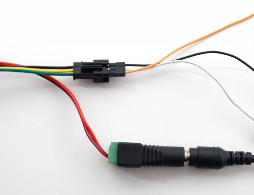
The wires on the 3-JST SM connector are then connected to your microcontroller: black is ground, yellow is data and green is clock.
Driver Chip
Each pixel contains a small microchip within the silicone dot. The WS2801 LED driver chip is custom designed for this purpose. These chips are very simple to communicate with — all they do is shift color data in from one pin and out another. To issue data from a microcontroller such as an Arduino, one "shifts out" 24 bits of color information — the first data out corresponds to the pixel closest to the microcontroller. To write data to 10 LEDs, you would issue 240 bits (10 * 24). Following the data, a 500 microsecond pause will "latch" the data and show the new LED colors.
The WS2801 chip is the same as in our 12mm pixels, so any software that works with the smaller pixels can also control these larger versions!
Wiring
The great thing about these pixels is that they're digitally controlled…that is, even though there are only two control lines (data and clock inputs), you can put as many pixels as you'd like in a single long strand, yet each one remains independently controllable.
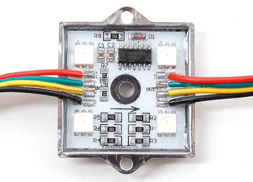
Though it looks like the 4-conductor ribbon cable is continuous, it isn't! The ground and 12V lines pass through from one pixel to the next, but the two data control lines are different on the input and output sides. The input side goes to the LED driver chip, which then drives its own output to the next pixel in the strand.
When connecting these pixels to a microcontroller, make sure you're connecting to the strand's input pins! On these large pixels, it's easy to spot: examine the circuit board, looking for the "IN" label and an arrow indicating the direction of data flow. If connecting multiple strands together, make sure the output of one strand goes to the input of the next.
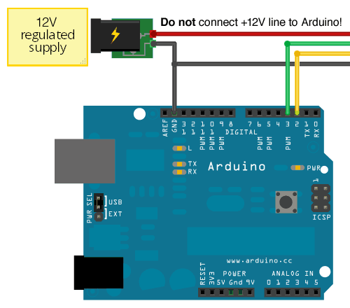
Wiring is pretty easy since there are only 4 wires. The only important thing is that you should not try to power the LED strand from the Arduino's 5V line — these LEDs require a dedicated 12V source separate from the microcontroller.
Use this diagram with the red wire going to +12V from the power supply, green (serial clock) to Arduino digital pin 3, yellow (serial data) to digital pin 2, and black to both the ground connection on the power supply and any available GND pin on the Arduino.
Our Arduino library (explained below) can use any two pins, but the examples are written to use pins 2 and 3 as above.
Download
To download the Arduino library, visit the repository on GitHub.
Click the DOWNLOAD ZIP button near the upper left, extract the archive and then rename the uncompressed folder to Adafruit_WS2801. Confirm that this folder contains the files Adafruit_WS2801.cpp and Adafruit_WS2801.h and the examples folder.
Place the WS2801 folder inside your Arduino Libraries folder. You may need to create this folder if it does not yet exist. In Windows, this would be (home folder)\My Documents\Arduino\Libraries and for Mac or Linux is (home folder)/Documents/Arduino/Libraries We also have a tutorial on library installation.
After installing the Adafruit_WS2801 library, restart the Arduino IDE. You should now be able to access the sample code by navigating through menus in this order: File→Sketchbook→Libraries→Adafruit_WS2801→strandtest
Code!
Let's look through the strandtest example code. To use the library in an Arduino sketch, you'll first need to globally declare a Adafruit_WS2801 object to talk to the strip. It is invoked with three variables: the number of pixels and the data and clock pins:
int dataPin  = 2;
int clockPin = 3;

// Set the first variable to the NUMBER of pixels. 25 = 25 pixels in a row
Adafruit_WS2801 strip = Adafruit_WS2801(25, dataPin, clockPin, WS2801_GRB);
The last parameter there, WS2801_GRB, is required when using these 36mm pixels (otherwise red and green will be reversed). You do NOT need this parameter if using our 12mm pixels.
Next, we initialize the strip in the setup() procedure:
void setup() {

  strip.begin();

  // Update LED contents, to start they are all 'off'
  strip.show();
}
begin() initializes the library, while show() refreshes the displayed colors of the LEDs. You'll need to call show() after changing any pixel colors to see this reflected in the LEDs. This way you can change the entire strip at one time (it takes the same amount of time to change one pixel as it does for an entire strip, because the full strip data must be issued regardless).
Let's look inside an example function, colorWipe(). This creates a 'chase' sequence that fills the strip up with a color. It is basically a loop that increments through every pixel (which you can query with the numPixels() function) and sets the color of each (incremented with i) to the value passed (c — colors are expressed as a 32-bit variable type, though only the bottom 24 bits are used). The strip output is then updated with show(). Finally there is some delay (otherwise this would happen instantly).
Below that is a helper function that converts a color from separate 8-bit red, green and blue values into a combined 24-bit value (suitable for passing to colorWipe()). The brightness range is from 0 (off) to 255 (max brightness).
// fill the dots one after the other with said color
// good for testing purposes
void colorWipe(uint32_t c, uint8_t wait) {
  int i;

  for (i=0; i < strip.numPixels(); i++) {
      strip.setPixelColor(i, c);
      strip.show();
      delay(wait);
  }
}

/* Helper functions */
// Create a 24 bit color value from R,G,B
uint32_t Color(byte r, byte g, byte b)
{
  uint32_t c;
  c = r;
  c <<= 8;
  c |= g;
  c <<= 8;
  c |= b;
  return c;
}
For example, in the loop() function we call colorWipe(Color(255, 0, 0), 50) which will fill the strand with full-brightness red light, pausing about 50 milliseconds between pixels.
  colorWipe(Color(255, 0, 0), 50);  // red fill
  colorWipe(Color(0, 255, 0), 50);  // green fill
  colorWipe(Color(0, 0, 255), 50);  // blue fill
