Table of Contents
This lovely little display breakout is the best way to add a small, colorful and bright display to any project. Since the display uses 3-wire SPI to communicate and has its own pixel-addressable frame buffer, it can be used with every kind of microcontroller. Even a very small one with low memory and few pins available!
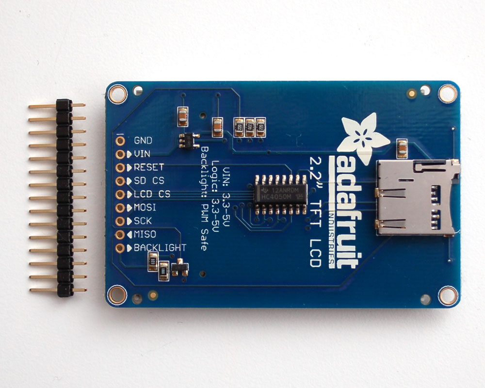
The 2.2" display has 220x176 color pixels. Unlike the low cost "Nokia 6110" and similar LCD displays, which are CSTN type and thus have poor color and slow refresh, this display is a true TFT! The TFT driver (HX8340) can display full 18-bit color (262,144 shades!). And the LCD will always come with the same driver chip so there's no worries that your code will not work from one to the other.
The breakout has the TFT display soldered on (it uses a delicate flex-circuit connector) as well as a ultra-low-dropout 3.3V regulator and a 3/5V level shifter so you can use it with 3.3V or 5V power and logic. We also had a little space so we placed a microSD card holder so you can easily load full color bitmaps from a FAT16/FAT32 formatted microSD card. The microSD card is not included, but you can pick one up here.
Flexible Wiring
Start by connecting a piece of header to the display. This will make breadboarding much easier. Break off a piece of 0.1" header 9 pins long and place it into a breadboard, long pins facing down into the breadboard
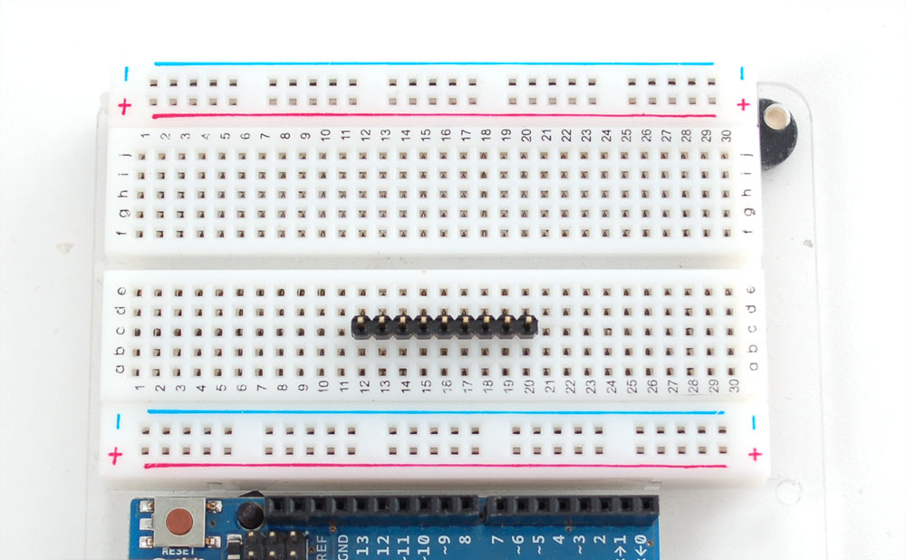
Place the display on top
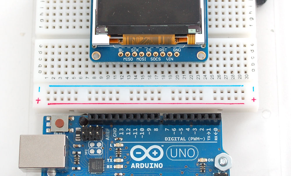
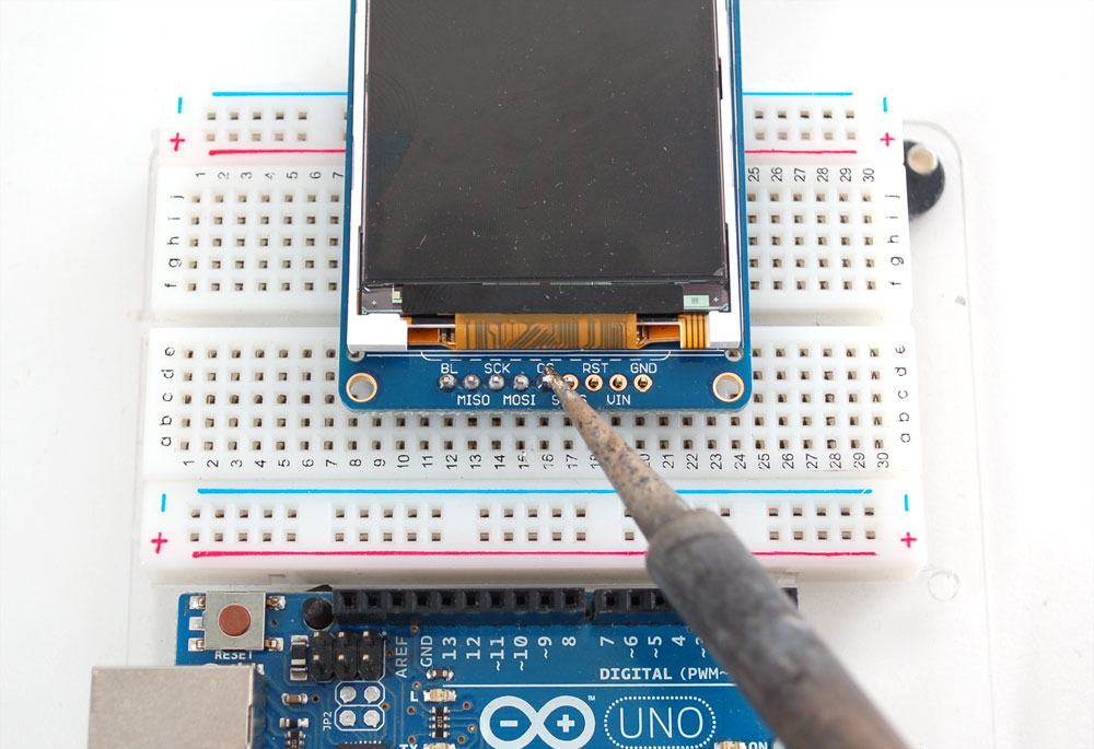
Solder all the pins
There are two ways to wire up these displays - one is a more flexible method (you can use any pins on the Arduino) and the other is much faster (4-8x faster, but you are required to use the hardware SPI pins) Since the display is quite large, we found that drawing would seem really slow if using 'software' SPI. For that reason, we'll show primarily how to wire up using hardware SPI and then how you can change the pins if desired
Hardware SPI means that we have to connect the CLK and MOSI pins to fixed digital pins. On '328 and '168 Arduinos, CLK must connect to digital 13 and MOSI must connect to digital 11. (If using an Arduino Mega, connect CLK to 52 and MOSI to 51.)
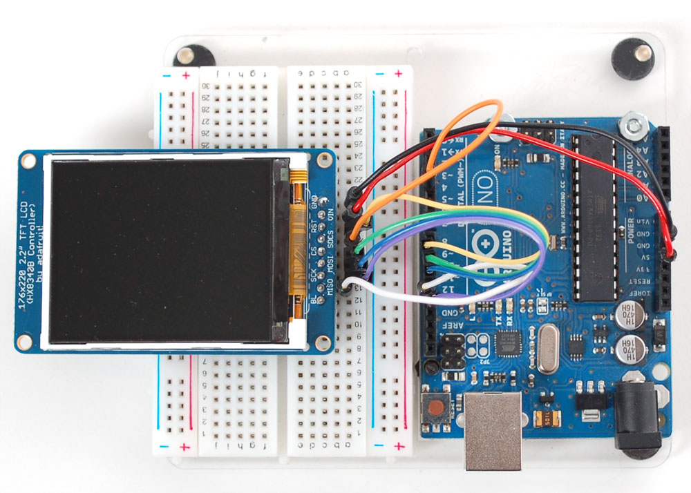
Digital 10 (53 on Arduino Mega) must also be an output (but doesn't need to be connected to any particular pin). We'll use the following pin connections:
- GND connecs to ground - black wire
- VIN connects to +5V - red wire
- RST (reset) connects to digtal 9 - yellow wire
- Skip SDCS (SD card chip select)
- CS (chip select) connects to digital 10 (or pin 53 on Arduino Mega) - green wire
- MOSI (data out) connects to digital 11 (51 on Mega) - blue wire
- SCK (clock) connects to digital 13 (52 on Mega) - purple wire
- Skip MISO (data in)
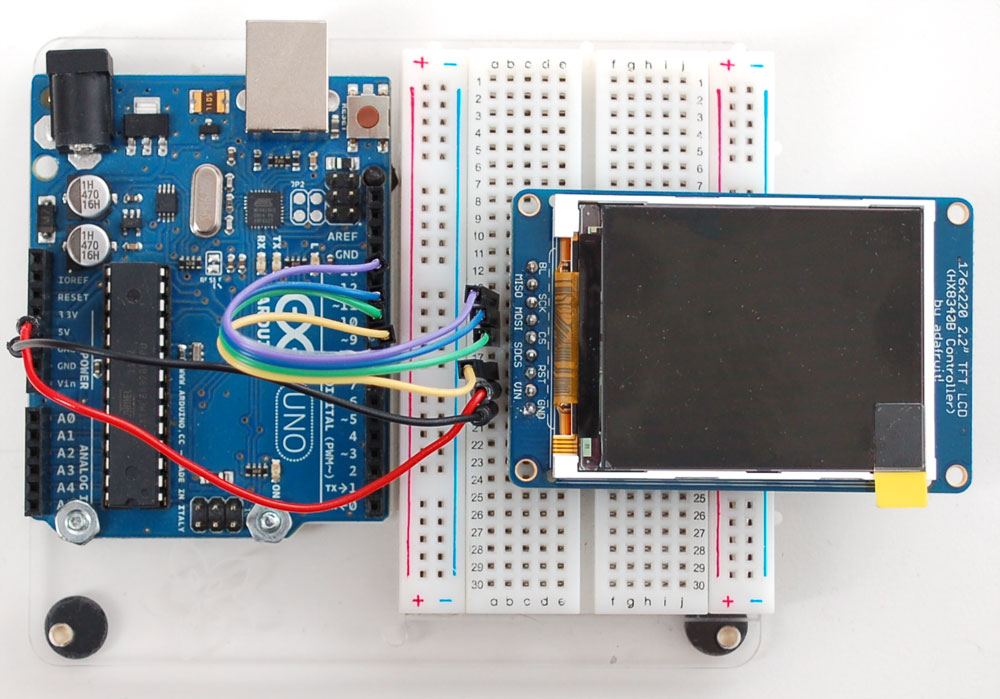
You can later change the CS and RST pins but to match the tutorial, use this connection diagram.
Test Display
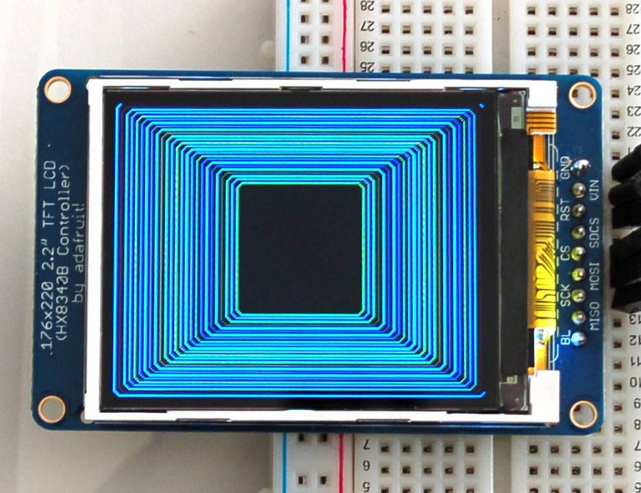
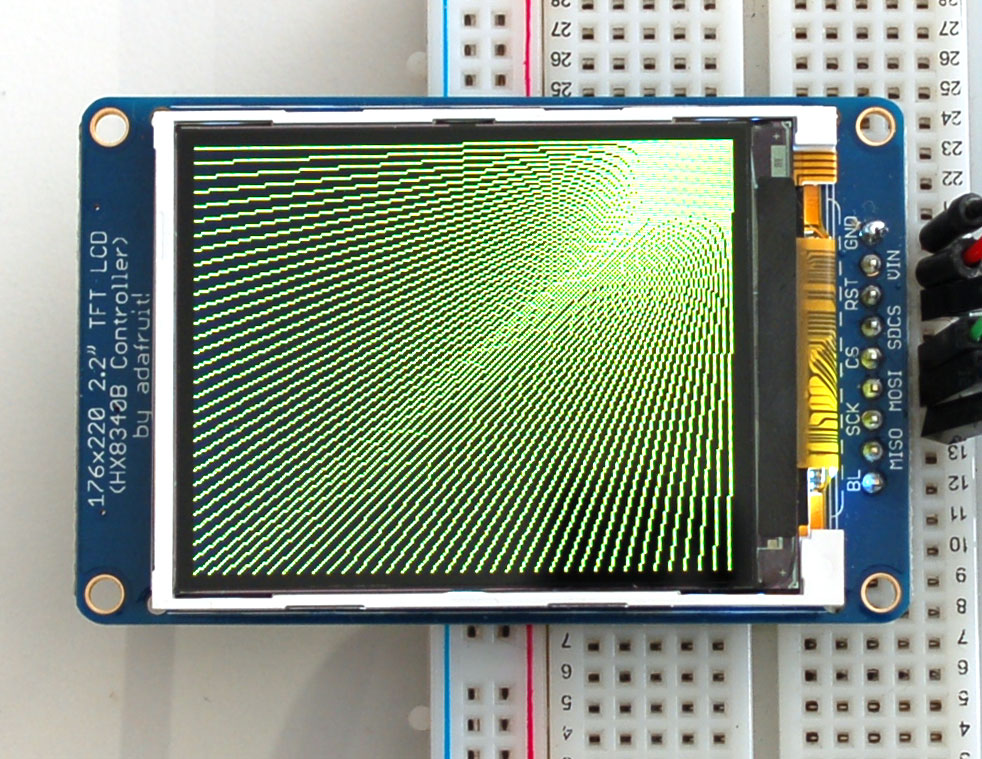
Once you have the display wired up, its time to test your wiring by uploading the example code we have written. Again, we suggest using an Arduino to test.
Download our Arduino library (see bottom of page) from github by clicking on Download in the top right corner. Uncompress the folder and rename it Adafruit_HX8340B - inside the folder you should see the Adafruit_HX8340B.cpp and Adafruit_HX8340B.h files. Install the Adafruit_HX8340B library foler by placing it in your arduinosketchfolder/libraries folder. You may have to create the libraries subfolder if this is your first library. You can read more about installing libraries in our tutorial
You will also need to get the GFX graphics core and click on the Downloads button in the top right corner to download a zip of the library and examples. Uncompress the folder and rename it Adafruit_GFX make sure that inside that folder is the cpp and .h files. Then copy it to your arduinosketchfolder/libraries folder.
Restart the Arduino IDE. You should now be able to select File > Examples > Adafruit_HX8340B > graphicstest sketch. Upload the sketch to your Arduino wired as above.
Once uploaded, the Arduino should perform all the test display procedures! If you're not seeing anything - first check if you have the backlight on, if the backlight is not lit something is wrong with the power/backlight wiring. If the backlight is lit but you see nothing on the display make sure you're using our suggested wiring
Graphics Library
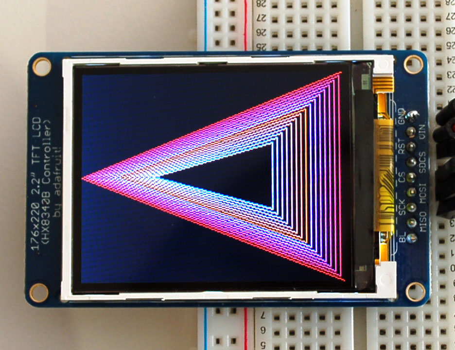
We've written a full graphics library specifically for this display which will get you up and running quickly. The code is written in C/C++ for Arduino but is easy to port to any microcontroller by rewritting the low level pin access functions. Here are some of the functions we've included in the library
The TFT LCD library is based off of the Adafruit GFX graphics core library. GFX has many ready to go functions that should help you start out with your project. Its not exhaustive and we'll try to update it if we find a really useful function. Right now it supports pixels, lines, rectangles, circles, round-rects, triangles and printing text as well as rotation.
Bitmaps
In this example, we'll show how to display a 220x176 pixel full color bitmap from a microSD card
We have an example sketch in the library showing how to display full color bitmap images stored on an SD card. You'll need a microSD card such as this one . You'll also need to download our SD library modified to allow faster reads (these changes will hopefully be added to arduino v23) but for now you can download the new library here . Download the library by clicking the Downloads button and uncompressing the folder. Replace the files in your ArduinoIDE/libraries/SD folder (make a backup of course) and restart the IDE.
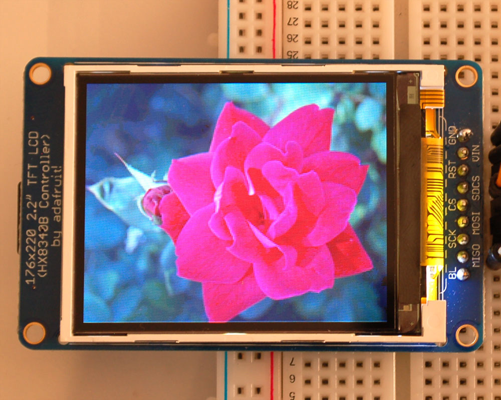
You'll also need an image. We suggest starting with this bitmap of a rose. If you want to later use your own image, use an image editing tool and crop your image to no larger than 160 pixels high and 128 pixels wide. Save it as a 24-bit color BMP file - it must be 24-bit color format to work, even if it was originally a 16-bit color image - becaue of the way BMPs are stored and displayed!
Names for bitmap files must not exceed 8 characters with a 3 character extension. "mybitmap.bmp" is fine. "myotherbitmap.bmp" is too long and will not be readable by the SD file system.
Copy the rose.bmp to the microSD card and insert it into the back of the breakout board
Wire up the TFT according to the high-speed SPI diagram above. Test that your wiring is correct by uploading the graphics test sketch with the high speed SPI line uncommented and the flexible-low-speed wiring commented.
Once you are sure that the TFT is wired correctly, add the two wires for talking to the SD card. Connect CDCS (the unconnected pin in the middle) to digital pin 4 (you can change this later to any pin you want) that's the orange wire below. Connect MISO (last unconnected pin) to the Arduino's hardware SPI MISO pin, that's the white wire below. For Classic arduinos, this is pin 12. For Mega's this is pin 50. You can't change the MISO pin, its fixed in the chip hardware
Now load the bitmap example sketch into the Arduino. It should display the parrot image. If you have any problems, check the serial console for any messages such as not being able to initialize the microSD card or not finding the image.
Alternative wiring
If you don't want to use the hardware SPI pins, its easy to adjust the example sketches. Look for the top section where you can call the constructor as Adafruit_HX8340B display(OLED_MOSI, OLED_CLK, OLED_RESET, OLED_CS). When all 5 arguments are passed to the display, it will automatically use the slower non-hardware-SPI interface. So you could uncomment that line and use any 5 pins you want.
// Option 1: use any pins but much slower
//Adafruit_HX8340B display(OLED_MOSI, OLED_CLK, OLED_RESET, OLED_CS);

// Option 2: must use the hardware SPI pins
// (for UNO thats sclk = 13 and sid = 11) and pin 10 must be
// an output. This is much faster - also required if you want
// to use the microSD card (see the image drawing example)
Adafruit_HX8340B display(OLED_RESET, OLED_CS);
You cannot use software SPI if drawing image bitmatps from the SD card since the SPI interface is shared with the microSD card socket.
There's one last pin, the BL pin, which is used to control the backlight. By default the backlight is always on. You can control it, turning it off or PWM dimming, by connecting a digital/PWM pin. The backlight draws up to 50mA but there's a transistor wired up so you will find that you can use a 'weak' microcontroller pin to drive all 3 LEDs.
Download
You can download our Arduino library with examples from github . To install it, rename the downloaded and uncompressed library to Adafruit_HX8340B and place in the sketchfolder/libraries folder. See our detailed tutorial for more info.
You will also have to get the latest Adafruit GFX library, which is the underlying graphics core. Install it just like the above
You may also be interested in the datasheet for the display , and display driver chip
