Table of Contents
What it is...
- Type: Graphical (128x64) monochrome LCD with LED backlight
- Interface: Serial / SPI
Introduction
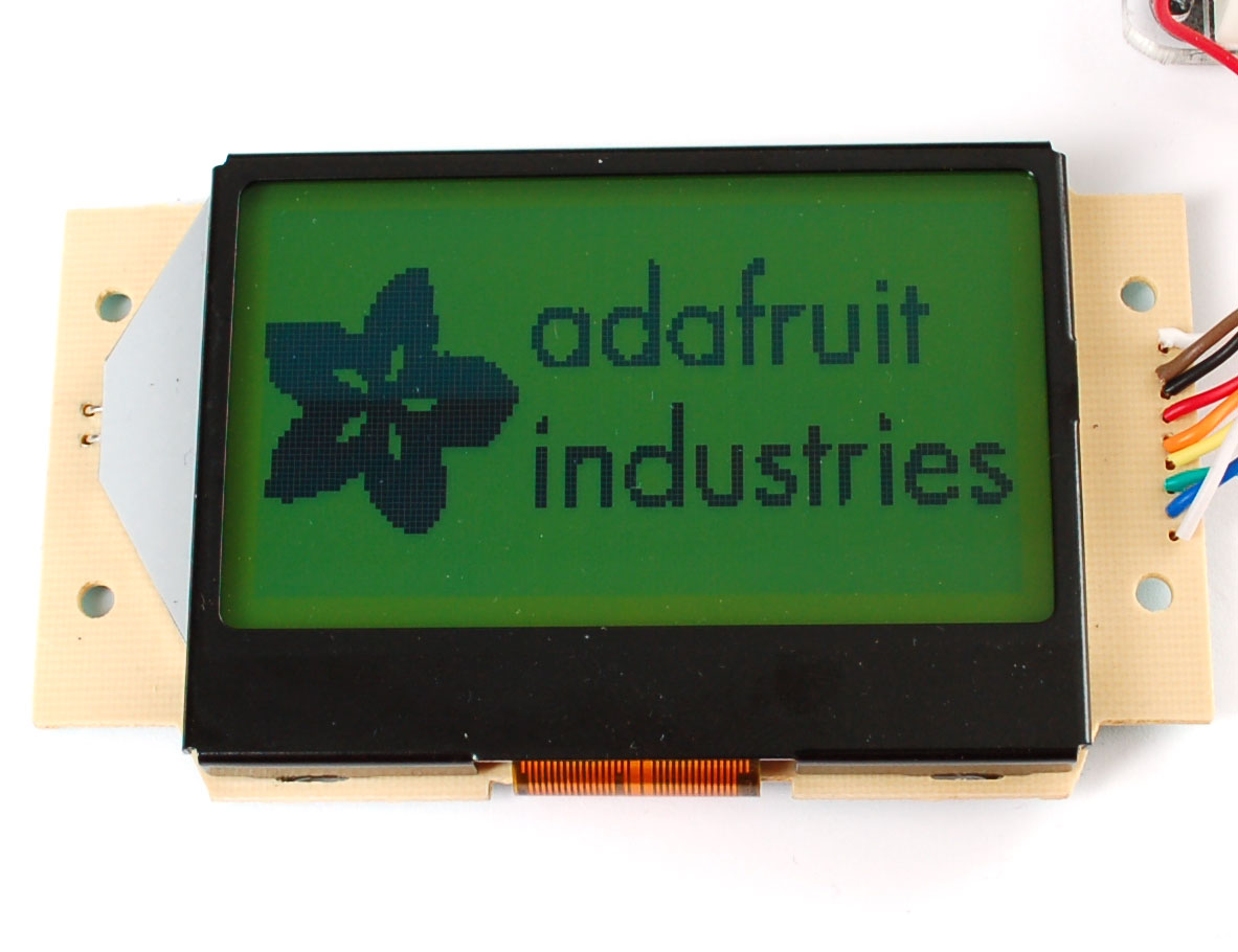
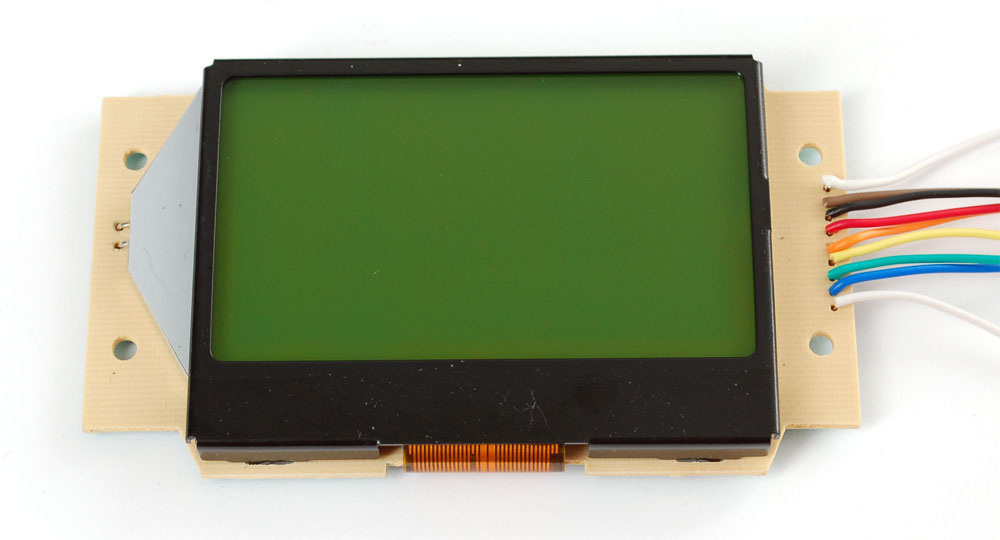
This mini-tutorial will go through the process of setting up a ST7565 LCD. These LCDs are graphical which means they can display pixels, not just text. This type of LCD in particular has 128x64 pixels, whch appear dark gray on a green-blue background. They have a backliight but can also be used without the light on for daytime visibility.
Another kind of LCD is the KS0108-type. These are not the same and are not compatible! Here are some comparisons
| KS0108 | ST7565 | |
|---|---|---|
| Voltage | 5V | 3.3V |
| Interface | Parallel | Serial |
| Data pins needed | 14 | 4 or 5 |
| Display size | 128x64 | 128x64 |
| Contrast adj. | requires potentiometer | internal, no extras! |
| Buffer needed? | No | Yes |
As you can see there are a few differences.
- For one the ST7565 runs at 3.3V not 5. This means a buffer chip or level shifting is necessary, you can use resistors or a chip like the 4050 (or equiv).
- Second, the interface is Serial (one bit at a time) instead of Parallel (8 bits at a time). This means it uses waaay fewer pins (yay!)
- The biggest downside is that you can't read from the LCD in serial mode, only write. This means that the chip has to keep track of the display (the KS0108 lets you read or write). So whatever microcontroller you use will need to spend 1024 bytes (1Kb) of RAM on the display memory. For some chips this is a little and some its a lot - you will need to check the micro's datasheet.
If you are using an ATmega168 or ATmega8 such as used in older Arduinos you must upgrade to a '328 to use this LCD. And if you're using a '328 note that half the RAM is going to the display so you wont have a lot left over. This pretty much means you can't use something with an SD card (like a Wave Shield or Data logger Shield at the same time you will straight-up run out of RAM and it will be wierd so dont bother).
Get the code!
We've written a tidy library for both C and Arduinoese, if you aren't using an AVR the C code is very portable and should take only a few minutes to turn into your favorite microcontroller.
Download it from github - click **Download Source** to grab it all. If you are using an Arduino, install the **ST7565 **folder which contains the library and an example sketch
Wire it up!
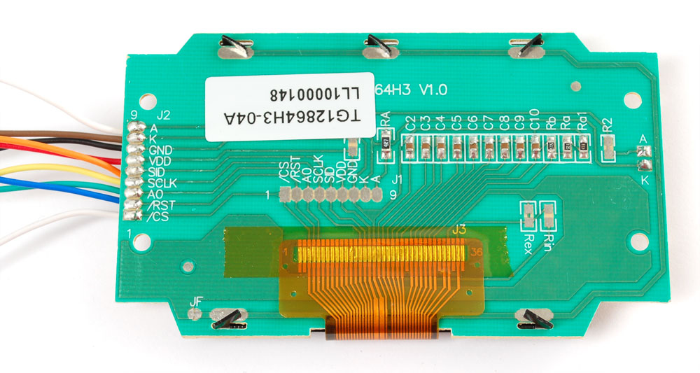
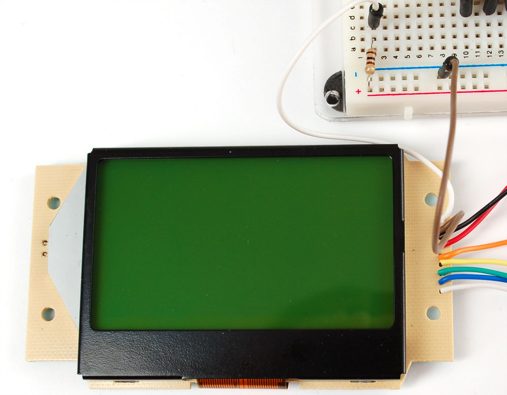
We'll begin by soldering wires to the LCD. I'll use rainbow wires to make it a bit easier to tell apart but you can use whatever you'd like. The pitch of the connector is 2mm which means it wont fit into a breadboard but wires are easy to add on.
Here are the wire colors and the pins they go to:
- /CS - Chip Select - White
- /RST - Reset - Blue
- A0 - sometiimes called RS - Green
- SCLK - Serial clock - Yellow
- SID - Serial Input Data - Orange
- VDD - 3.3V power - Red
- GND - ground - Black
- K - LED cathode - Brown
- A - LED anode - White

In this tutorial we assume you're using a 5V microcontroller such as an Arduino, if your chip is runninag at 3v, you can basically just ignore the 4050 and do everything else!
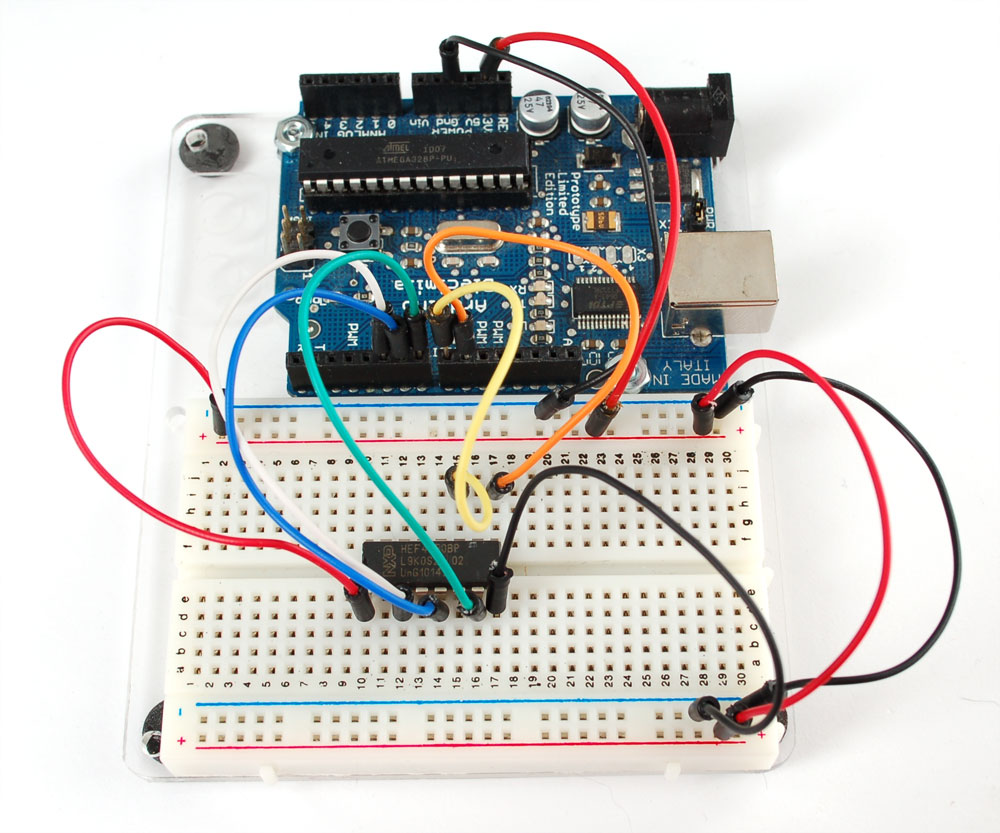
The 4050 is a chip that will convert the high voltage of 5V down to 3V, here is a diagram

Start by connecting pin 1 of the 4050 (red) of the chip to 3.3V and pin 8 of the 4050 (black) to ground. In the following image, the two rails on the side are connected to the Ground and 3V pin from the Arduino.
Then connect:
- Digital 9 of the Arduino to pin 9 of the 4050 - Orange
- Digital 8 of the Arduino to pin 11 of the 4050 - Yellow
- Digital 7 of the Arduino to pin 7 of the 4050 - Green
- Digital 6 of the Arduino to pin 5 of the 4050 - Blue
- Digital 5 of the Arduino to pin 3 of the 4050 - White
Click on the photo for a bigger view if you need help with the wiring
Now the 4050 is connected to the Arduino we can connect the LCD up. We'll start with the backlight (whch is optional) Brown (K) connects to ground and White (A) connects through a ~100 ohm resistor to 3V. You can also connect it to 5V through a ~270 resistor. Be sure to have some sort of resistor!
Finally the LCD power and data lines. Connect Red (VDD) to 3.3V and Black (GND) to ground. Then connect
- Orange (SID) to pin 10 of the 4050
- Yellow (SCLK) to pin 12 of the 4050
- Green (A0) to pin 6 of the 4050
- Blue (/RST) to pin 4 of the 4050
- White (/CS) to pin 2 of the 4050

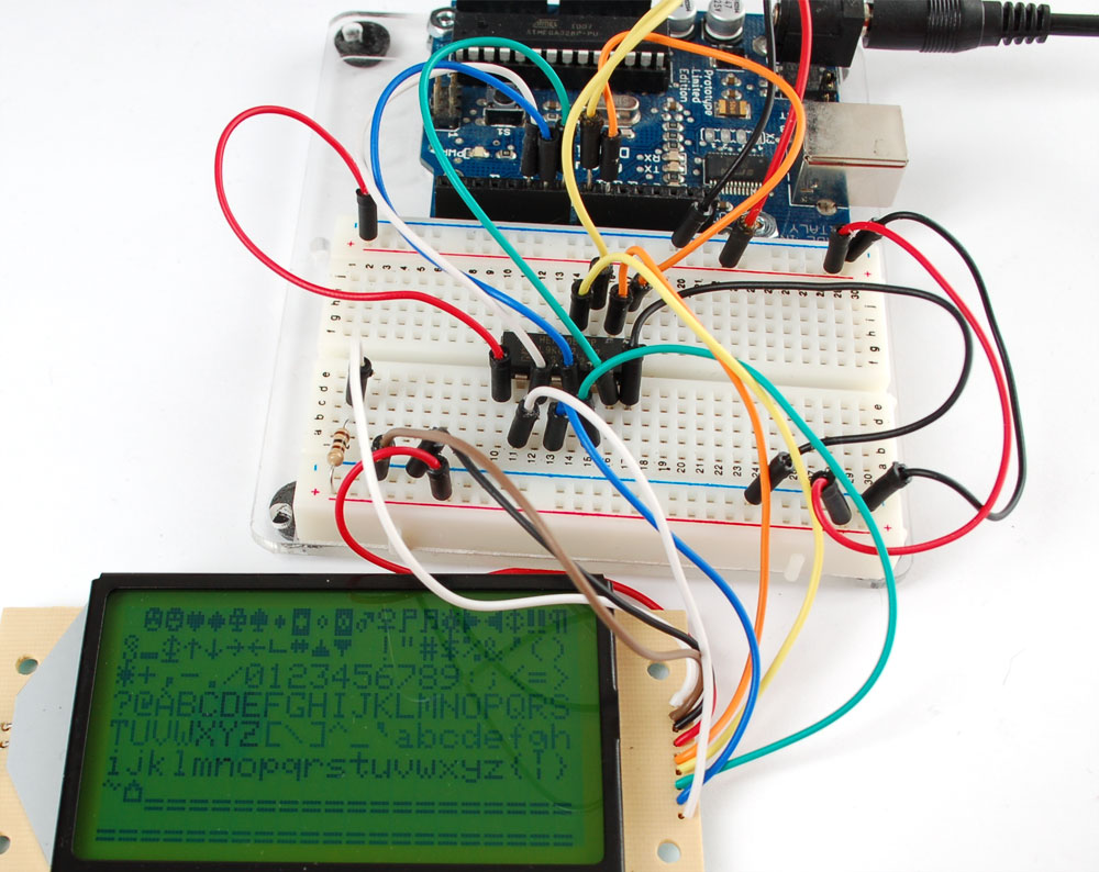
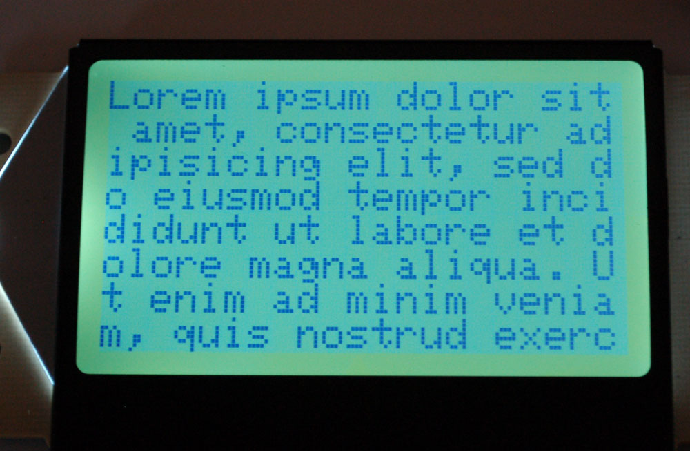
Now you can run the ST7565 example sketch in the library which will show off some of the many ways you can use the screen.
Enjoy!
