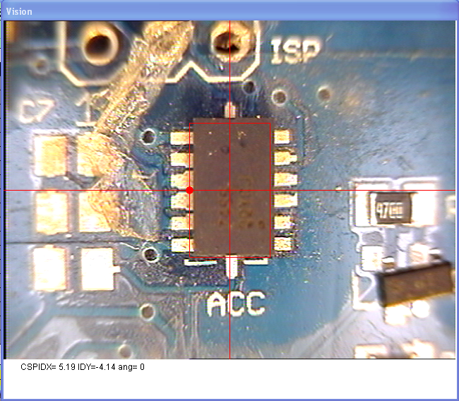
Partial assembly
Once you have your part defined and tested and the part positioned on the PCB you will want to test placement. This test goes through the part vision recognition and placement. we often test one part at a time, setting the Tape Feeder Index to 0 for bigger parts so we can just pull the part off and try again over and over.
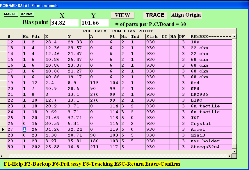
First, go to the PCB parts definition spreadsheet. Press 2 (edit) and 2 (change data) then navigate to the part you want to place (like our accelerometer)
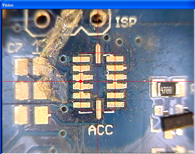
Press F8 of course, to place the outline where you want it to go.
Once you're happy, press escape and then return to enter in the new location.
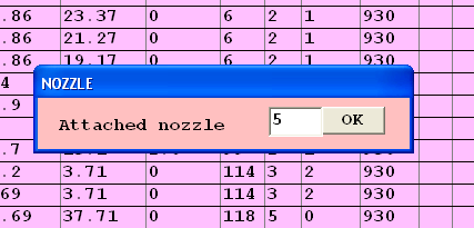
Now press F6 (Prtl assy in the bottom of the spreadsheet window) - if you need to swap nozzles to pick up the part the machine will automagically ask you to do a nozzle change. Tell it what nozzle is currently in the machine.
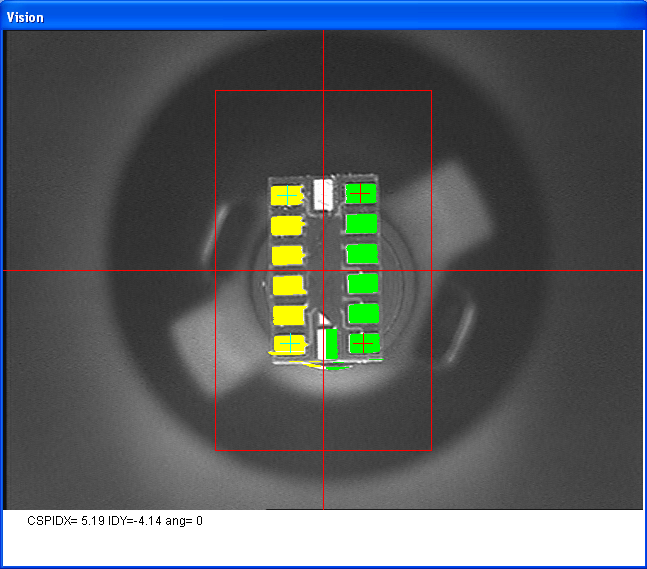
The vision test and placement should commence
If you have problems, you can fix them now by adjusting the part definition or location.
Hint Using double-sticky tape on the PCB will make it really easy to do these tests. We always have one PCB that is covered in double-sided tape!

