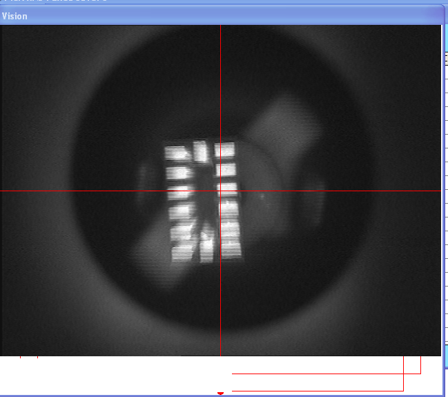
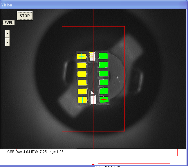
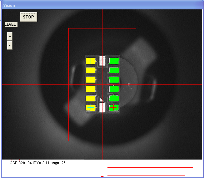
We were having difficulty with the MDC vision placement for our leadless parts. When we did a parts test, the vision worked fantastic:
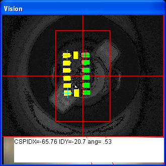
But when it came to placement, the parts were always shifted or skewed :(
I knew the part definition was OK - but during test, it would try 3 or 4 times to center the part. Whereas for assembly it would take one photo and take it from there. Much sadness.
Then I found out that you could make the assembly mode use the 'Closed Loop' vision system. Having taken a Signals and Systems class, I liked the sound of that!
In assembly mode, we have feature so called closed loop which repeat measuring until the target tilt reaches the limit looks like shift+P.
checking your system constant when shipped out, k11's remark starts as " LOse" and if you change it as "CLOse" it become closed loop. (actually first C  makes closed loop)
And k11's first value is the angle limit for parts from tape or stick tube and 30 is approx one degree. current value is 5 and it may too small try 10  (0.3deg)
(2nd value is for parts from tray but also 3 will be too small)
Also the last of remark of  k7' is 10 . This is waiting time for image capture but for closed loop you may better to increase to say 90.
OK so we went to the System Constant spreadsheet and change the comment of k11 to "CLose…" (just the first character). We didn't change the angle limit (still trying to understand it) but we did set the k7 remark constant to 90
The machine now uses closed loop vision, it works much much better for the leadless parts. Will report back on more info


