Table of Contents
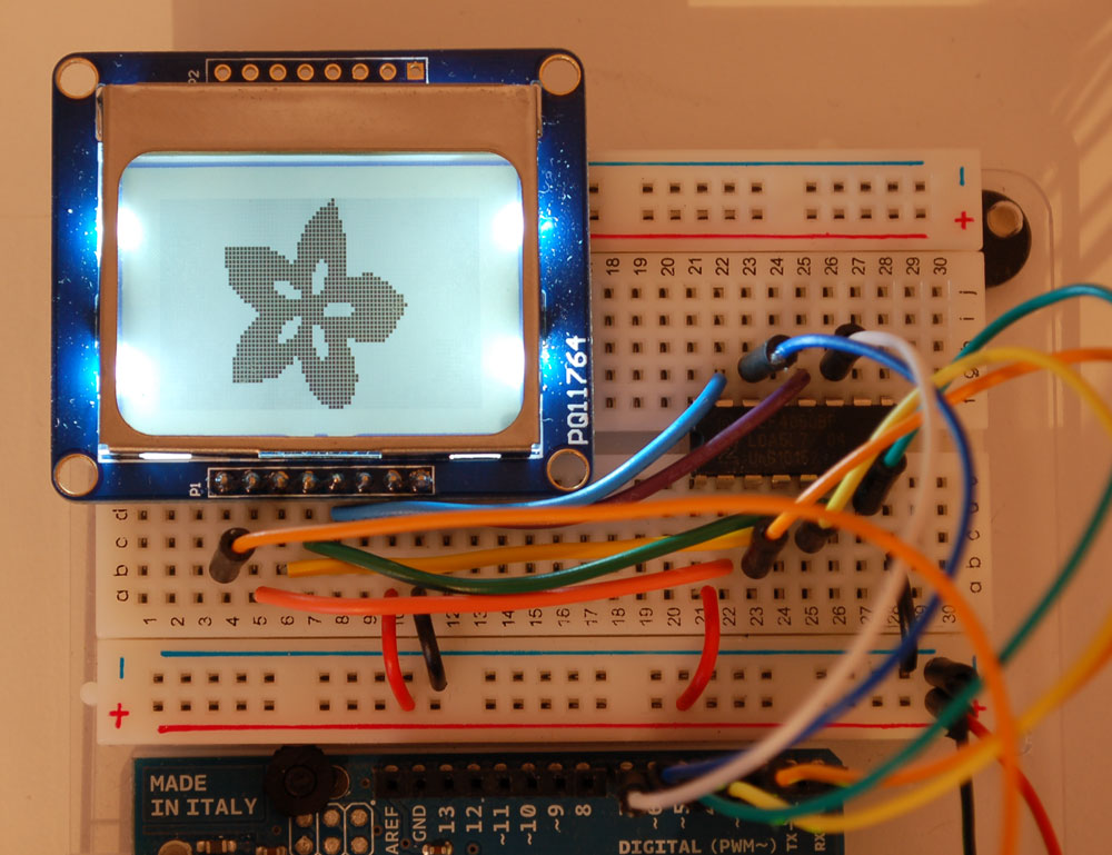
This is a quick tutorial for our 84x48 pixel monochrome LCD display. These displays are small, only about 1.5" diameter, but very readable due and comes with a backlight. This display is made of 84x48 individual pixels, so you can use it for graphics, text or bitmaps. These displays are inexpensive, easy to use, require only a few digital I/O pins and are fairly low power as well
To drive the display, you will need 3 to 5 digital output pins (depending on whether you want to manually control the chip select and reset lines). Another pin can be used to control (via on/off or PWM) the backlight. To make things easy for you, we've written a nice graphics library that can print text, pixels, rectangles, circles and lines! The library is written for the Arduino but can easily be ported to your favorite microcontroller.
Power requirements
The display uses the PCD8544 controller chip from Philips and were used in Nokia 3310 and 5110 cell phones. This chip is designed to run only at 3.3V and have 3v communication levels, so for 5V microcontrollers a logic level shifter is required (otherwise you could easily damage the display)
If you want to use the backlight, that can draw up to 80mA (4 white LEDs at 20mA each). The backlight pin is connected to a transistor so you can PWM all 4 LEDs at once from a microcontroller pin.
Wiring
The LCD runs at 3.3V so you'll need to use a level shifting chip to use with a 5V microcontroller. The following will assume that is the case. If you're running a 3.3V microcontroller system, you can skip the level shifter.
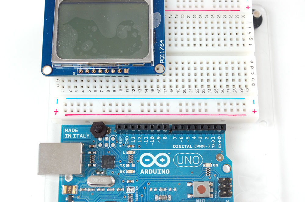
We'll assume you want to use this in a breadboard, take a piece of 0.1" header 8 pins long and insert it into a breadboard
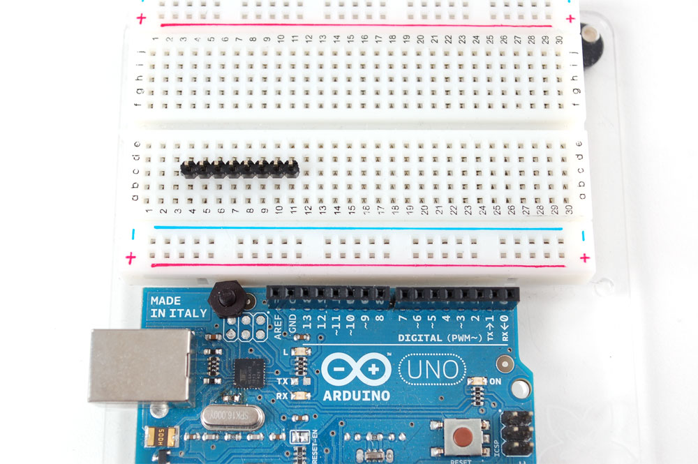
Slide either side of the LCD onto the header, the 'thicker' end is the top
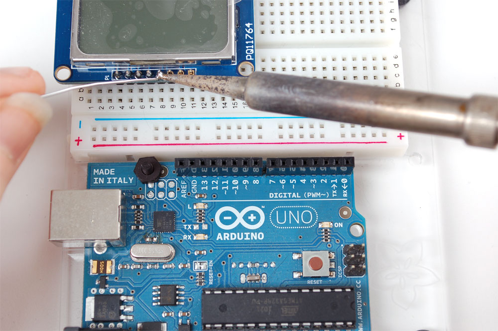
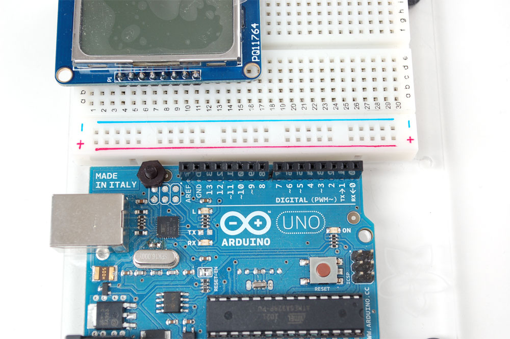
Solder all the pins
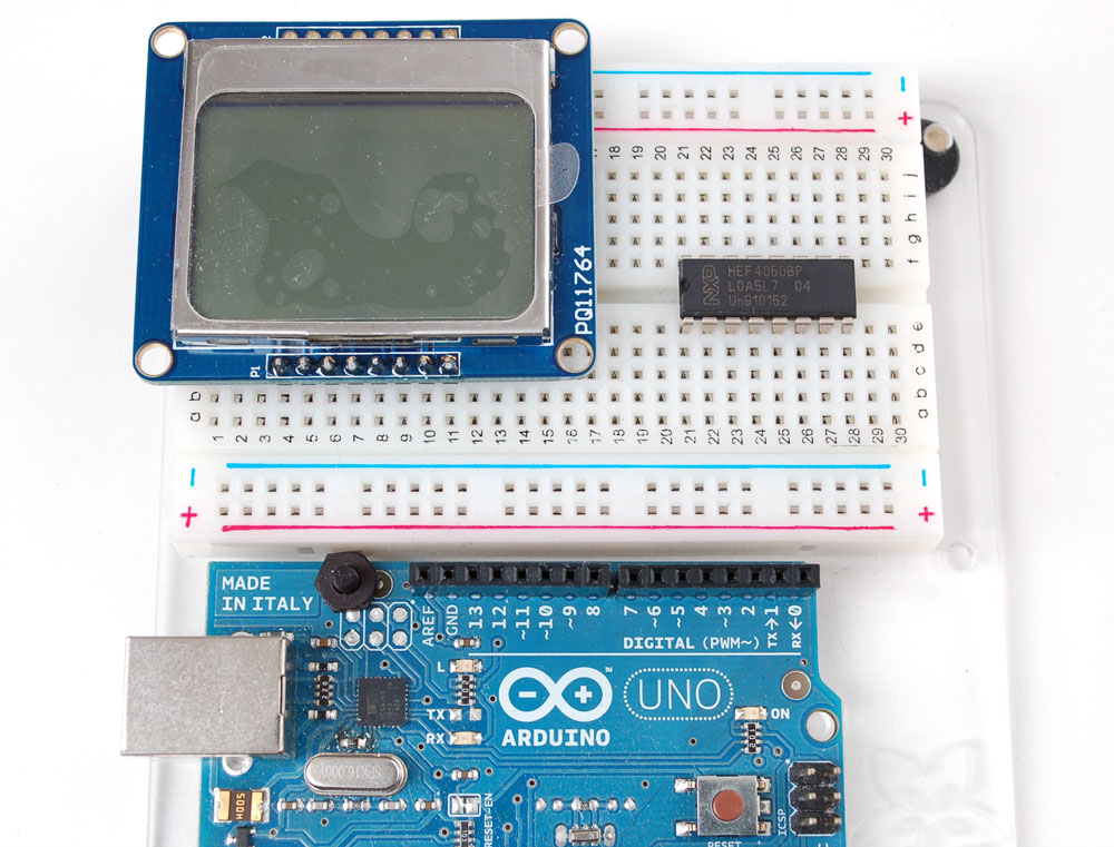
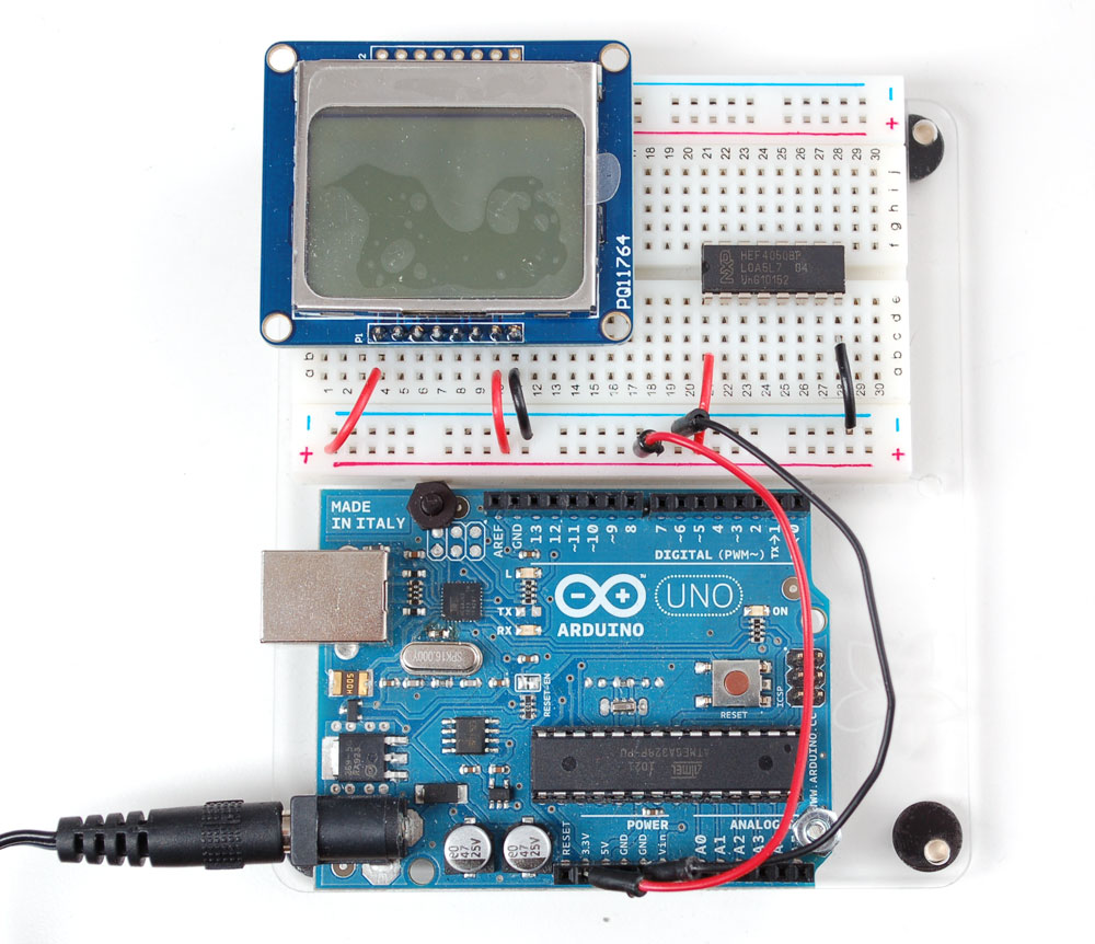
Place the level shifter chip off to the side. Pin 1 is on the left here.
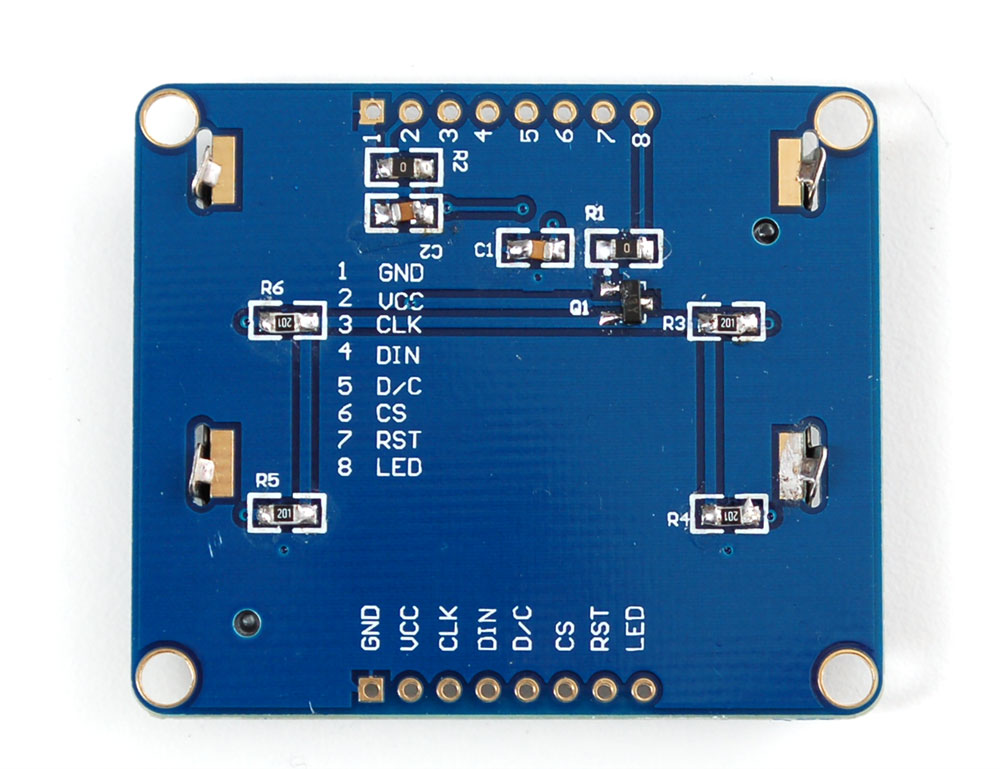
We'll start with the power lines. the system must be powered by 3.3V so red here is connected to the 3V pin from the Arduino. Ground is black.
- Connect pin 1 of the 4050, the LCD VCC pin and the LCD backlight pin to 3.3V.
- Connect pin 8 of the 4050 and the GND pin of the LCD to ground.
Verify you see the backlight LEDs light up
Next we'll start wiring up the data lines.
- Connect the RST (reset) pin of the LCD (orange wire) to pin 2 of the 4050
- Connect the CS (chip select) pin (yellow wire) to pin 4 of the 4050.
- Connect the D/C (data/command) pin (green wire) to pin 6 of the 4050.

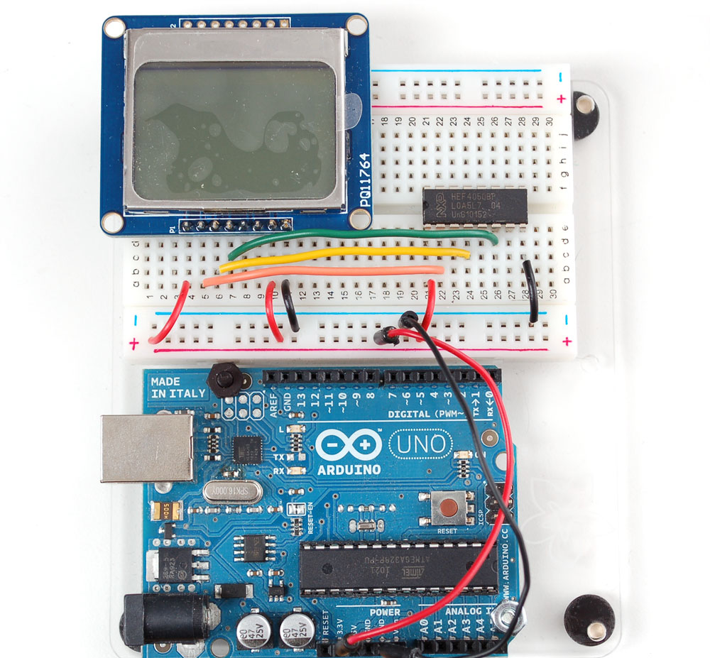
Next, connect:
- DIN (data in) pin (blue wire) to pin 15 of the 4050
- CLK(clock) pin (purple wire) to pin 12 of the 4050.
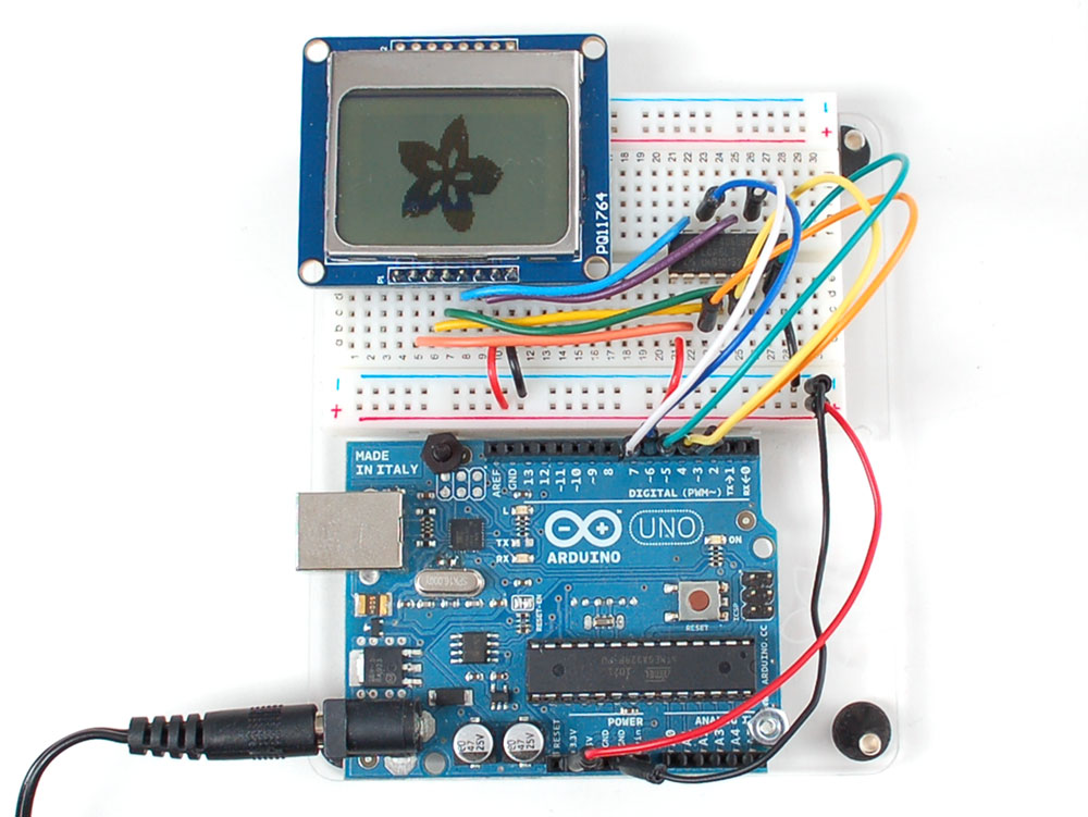
Then we can connect the data lines from the arduino to the LCD. We can use any 5 pins but you may want to start with our example first.
- Arduino pin 3 (orange) goes to pin 3 of the 4050.
- Arduino pin 4 (yellow) goes to pin 5 of the 4050.
- Arduino pin 5 (green) goes to pin 7 of the 4050.
- Arduino pin 6 (blue) goes to pin 14 of the 4050.
- Arduino pin 7 (violet) goes to pin 11 of the 4050.

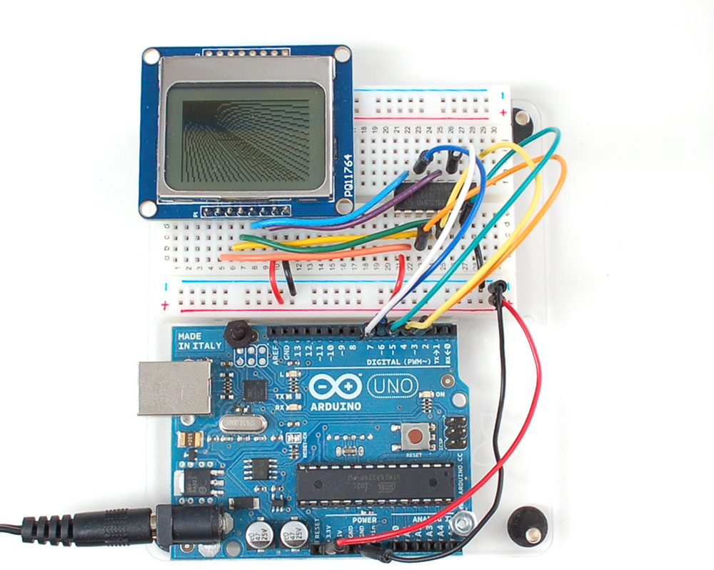
Now you are ready to test!
Testing
Download our Arduino library from github. Download it by clicking on the Download button and renaming the uncompressed folder PCD8544. Make sure that inside that folder you see the .cpp and .h files. Then copy the folder to your arduinosketchfolder/libraries folder. See our tutorial for more details.
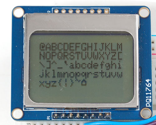
Restart the Arduino software. You should see a new example folder called PCD8544 and inside, an example called pcdtest. Open up that sketch and upload it to your Arduino. You should see the example test sequence.
You can control the backlight, its much brighter when you connect the backlight pin to 5V (you don't need a level shifter). You can control the backlight using an Arduino pin since there is a transistor on the board.
Graphics library
We have a ready to go basic graphics library that has primitives for bitmaps, shapes and text. You can probably do everything you want using it. Because of the way the display works we need to buffer the entire display in ram which is 84x48 bits (504 bytes). However, screen updates are very fast.
First up is the most basic pixel pusher. You can call this with two coordinates and a color (BLACK or WHITE) and it will make a dot:
void setPixel(uint8_t x, uint8_t y, uint8_t color);
You can also draw lines, with a starting and end point and color
void drawline(uint8_t x0, uint8_t y0, uint8_t x1, uint8_t y1, uint8_t color);
Next up, rectangles and squares can be drawn and filled using the following procedures.
void drawrect(uint8_t x0, uint8_t y0, uint8_t w, uint8_t h, uint8_t color);
void fillrect(uint8_t x0, uint8_t y0, uint8_t w, uint8_t h, uint8_t color);
Likewise, for circles, you can draw and fill
void drawcircle(uint8_t x0, uint8_t y0, uint8_t r,	uint8_t color);
void fillcircle(uint8_t x0, uint8_t y0, uint8_t r,	uint8_t color);
If you need to add some text, you can easily print text, variables, etc to any location on the display. We only have one 5x8 font but it works pretty well. First you need to set the top left corner where it will start to print the text
void setCursor(uint8_t x, uint8_t y);
Then you can use the standard print() and println() commands to draw text or variables, just like Serial
  nokia.setCursor(0, 0);
  nokia.print("Lorem ipsum dolor sit amet, consectetur adipisicing elit, sed do eiusmod tempor");
  nokia.println(0xAB, HEX);
  nokia.print(99.99);
  nokia.println('%');
You can draw small bitmaps, good for sprites and other minianimations or icons
void drawbitmap(uint8_t x, uint8_t y, const uint8_t *bitmap, uint8_t w, uint8_t h, uint8_t color);
After each change to the display you'll want to call
display();
Which will write your changes to the display.
These primitives should get you started!
Wiring (fewer pins)
You can save some pins by connecting the CS pin to ground (this means you cant reuse the LCD's pins between screen updates but maybe thats OK. You can also connect the RST pin to the Arduino reset so that it will reset the screen automatically.
Download
You can download our PCD8544 (Nokia 5110) LCD display Arduino library from github which comes with example code. This library uses 1/2 Kbytes of RAM since it needs to buffer the entire display but its very fast! The code is simple to adapt to any other microcontroller.
The PCD8544 datasheet tells you all about what the display can do
