Table of Contents

What is a thermistor?
A thermistor is a thermal resistor - a resistor that changes its resistance with temperature. Technically, all resistors are thermistors - their resistance changes slightly with temperature - but the change is usually very very small and difficult to measure. Thermistors are made so that the resistance changes drastically with temperature so that it can be 100 ohms or more of change per degree!
There are two kinds of of thermistors, NTC (negative temperature coefficient) and PTC (positive temperature coefficient). In general, you will see NTC sensors used for temperature measurement. PTC's are often used as resettable fuses - an increase in temperature increases the resistance which means that as more current passes thru them, they heat up and 'choke back' the current, quite handy for protecting circuits!
Thermistors have some benefits over other kinds of temperature sensors such as analog output chips (LM35/TMP36) or digital temperature sensor chips (DS18B20) or thermocouples.
- First off, they are much much cheaper than all the above! A bare 5% thermistor is only 10 cents in bulk.
- They are also much easier to waterproof since its just a resistor.
- They work at any voltage (digital sensors require 3 or 5V logic).
- Compared to a thermocouple, they don't require an amplifier to read the minute voltages - you can use any microcontroller to read a thermistor.
- They can also be incredibly accurate for the price. For example, the 10K 1% thermistor in the shop is good for measuring with ±0.25°C accuracy! (Assuming you have an accurate enough analog converter)
- They are difficult to break or damage - they are much simpler and more reliable
On the other hand, they require a little more work to interpret readings, and they dont work at very high temperatures like thermocouples. Without a digital-to-analog converter on board, you might be better off with a digital temperature sensor.
Their simplicity makes them incredibly popular for basic temperature feedback control. For example, lets say you wanted to have a fan that turns on when the temperature gets high. You could use a microcontroller, a digital sensor, and have that control the relay. Or you could use the thermistor to feed the base of a transistor, as the temperature rises, the resistance goes down, feeding more current into the transistor until it turns on. (This is a rough idea, you would need a few more components to make it work)
Even if you do use a microcontroller or complex system, for the price you can't beat 'em!
Some Stats
Here are technical details for the thermistor in our shop
- Resistance at 25°C: 10K ±1%
- B25/50: 3950 ±1%
- Thermal time constant ⇐ 15 seconds
- Thermistor temperature range -55°C to 125°C
- Wire temperature range -55°C to 105°C
- 28 AWG PVC Wire
- Diameter: 3.5mm/0.13in
- Length: 18in/45cm
Note that even though the thermistor can go up to 125°C the cable itself maxes out at 105°C so this thermistor is not good for measuring very very hot liquids
Testing your thermistor
Because thermistors are simply resistors, its easy to test it out. Simply measure the resistance using a multimeter:
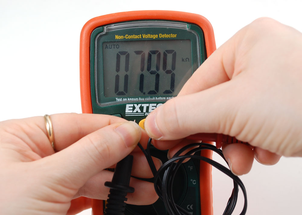
You should read about 10Kohm assuming its room temperature where you're sitting. The resistance of course may be higher or lower depending on the room temperature. For example, its warm here in an un-airconditioned room in the middle of the summer, so we read 8Kohm (30°C - 86°F!)
Connecting to your thermistor
These thermistors are pretty hardy, you can strip the PVC insulation and stick the wires into a breadboard or solder to them directly. Of course you can cut or extend the wires. Since the resistance is pretty high (10Kohm) the wire resistance won't make a huge difference.
Analog voltage reading method
To measure the temperature, we need to measure the resistance. However, a microcontroller does not have a resistance-meter built in. Instead, it only has a voltage reader known as a analog-digital-converter. So what we have to do is convert the resistance into a voltage, and we'll do that by adding another resistor and connecting them in series. Now you just measure the voltage in the middle, as the resistance changes, the voltage changes too, according to the simple voltage-divider equation. We just need to keep one resistor fixed
Say the fixed resistor is 10K and the variable resistor is called R - the voltage output (Vo) is:
Vo = R / (R + 10K) * Vcc
Where Vcc is the power supply voltage (3.3V or 5V)
Now we want to connect it up to a microcontroller. Remember that when you measure a voltage (Vi) into an Arduino ADC, you'll get a number.
ADC value = Vi * 1023 / Vcc
So now we combine the two (Vo = Vi) and get:
ADC value = R / (R + 10K) * Vcc * 1023 / Vcc
What is nice is that if you notice, the Vcc value cancels out!
ADC value = R / (R + 10K) * 1023
It doesn't matter what voltage you're running under. Handy!
Finally, what we really want to do is get that R (the unknown resistance). So we do a little math to move the R to one side:
R = 10K / (1023/ADC - 1)
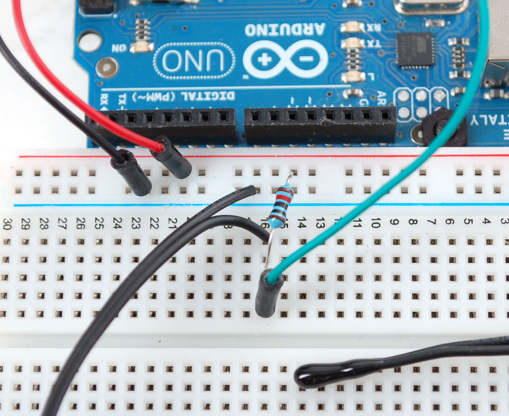
Great, lets try it out. Connect up the thermistor as shown:

Connect one end of the 10K resistor to 5V, connect the other end of the 10K 1% resistor to one pin of the thermistor and the other pin of the thermistor to ground. Then connect Analog 0 pin to the 'center' of the two.
Now run the following sketch:
// the value of the 'other' resistor
#define SERIESRESISTOR 10000

// What pin to connect the sensor to
#define THERMISTORPIN A0

void setup(void) {
  Serial.begin(9600);
}

void loop(void) {
  float reading;

  reading = analogRead(THERMISTORPIN);

  Serial.print("Analog reading ");
  Serial.println(reading);

  // convert the value to resistance
  reading = (1023 / reading)  - 1;
  reading = SERIESRESISTOR / reading;
  Serial.print("Thermistor resistance ");
  Serial.println(reading);

  delay(1000);
}
You should get responses that correspond to the resistance of the thermistor as measured with a multimeter
Better readings
When doing analog readings, especially with a 'noisy' board like the arduino, we suggest two tricks to improve results. One is to use the 3.3V voltage pin as an analog reference and the other is to take a bunch of readings in a row and average them.
The first trick relies on the fact that the 5V power supply that comes straight from your computer's USB does a lot of stuff on the Arduino, and is almost always much noisier than the 3.3V line (which goes through a secondary filter/regulator stage!) It's easy to use, simply connect 3.3V to AREF and use that as the VCC voltage. Because our calcuations don't include the VCC voltage, you don't have to change your equation. You do have to set the analog reference but that's a single line of code
Taking multiple readings to average out the result helps get slightly better results as well, since you may have noise or fluctuations, we suggest about 5 samples.
Rewire as shown:

This sketch takes those two improvements and integrates them into the demo, you will have better, more precise readings.
// which analog pin to connect
#define THERMISTORPIN A0
// how many samples to take and average, more takes longer
// but is more 'smooth'
#define NUMSAMPLES 5
// the value of the 'other' resistor
#define SERIESRESISTOR 10000

int samples[NUMSAMPLES];

void setup(void) {
  Serial.begin(9600);
  // connect AREF to 3.3V and use that as VCC, less noisy!
  analogReference(EXTERNAL);
}

void loop(void) {
  uint8_t i;
  float average;

  // take N samples in a row, with a slight delay
  for (i=0; i< NUMSAMPLES; i++) {
   samples[i] = analogRead(THERMISTORPIN);
   delay(10);
  }

  // average all the samples out
  average = 0;
  for (i=0; i< NUMSAMPLES; i++) {
     average += samples[i];
  }
  average /= NUMSAMPLES;

  Serial.print("Average analog reading ");
  Serial.println(average);
  // convert the value to resistance
  average = 1023 / average - 1;
  average = SERIESRESISTOR / average;

  Serial.print("Thermistor resistance ");
  Serial.println(average);

  delay(1000);
}
Converting to temperature
Finally, of course, we want to have the temperature reading, not just a resistance! If you just need to do a quick comparision circuit (if temperature is below X do this, if its above Y do that), you can simply use the temperature/resistance table which correlates the resistance of the thermistor to the temperature.
However, you probably want actual temperature values. To do that we'll use the Steinhart-Hart equation, which lets us do a good approximation of converting values. Its not as exact as the thermistor table (it is an approximation) but its pretty good around the temperatures that this thermistor is used.
![]()
However, this equation is fairly complex, and requires knowing a lot of variables that we don't have for this thermistor. Instead we will use the simplified B parameter equation
![]()
For this one we only need to know To (which is room temperature, 25 °C = 298.15 K) B (in this case 3950, the coefficient of the thermistor), and Ro (the resistance at room temp, in this case 10Kohm). We plug in R (resistance measured) and get out T (temperature in Kelvin) which is easy to convert to °C
The following sketch will calculate °C for you
// which analog pin to connect
#define THERMISTORPIN A0
// resistance at 25 degrees C
#define THERMISTORNOMINAL 10000
// temp. for nominal resistance (almost always 25 C)
#define TEMPERATURENOMINAL 25
// how many samples to take and average, more takes longer
// but is more 'smooth'
#define NUMSAMPLES 5
// The beta coefficient of the thermistor (usually 3000-4000)
#define BCOEFFICIENT 3950
// the value of the 'other' resistor
#define SERIESRESISTOR 10000

int samples[NUMSAMPLES];

void setup(void) {
  Serial.begin(9600);
  analogReference(EXTERNAL);
}

void loop(void) {
  uint8_t i;
  float average;

  // take N samples in a row, with a slight delay
  for (i=0; i< NUMSAMPLES; i++) {
   samples[i] = analogRead(THERMISTORPIN);
   delay(10);
  }

  // average all the samples out
  average = 0;
  for (i=0; i< NUMSAMPLES; i++) {
     average += samples[i];
  }
  average /= NUMSAMPLES;

  Serial.print("Average analog reading ");
  Serial.println(average);

  // convert the value to resistance
  average = 1023 / average - 1;
  average = SERIESRESISTOR / average;
  Serial.print("Thermistor resistance ");
  Serial.println(average);

  float steinhart;
  steinhart = average / THERMISTORNOMINAL;     // (R/Ro)
  steinhart = log(steinhart);                  // ln(R/Ro)
  steinhart /= BCOEFFICIENT;                   // 1/B * ln(R/Ro)
  steinhart += 1.0 / (TEMPERATURENOMINAL + 273.15); // + (1/To)
  steinhart = 1.0 / steinhart;                 // Invert
  steinhart -= 273.15;                         // convert to C

  Serial.print("Temperature ");
  Serial.print(steinhart);
  Serial.println(" *C");

  delay(1000);
}
For better precision, we suggest reading the exact value of the 'series 10K' it should be nearly exactly 10K but if you can get a better reading that will reduce your error
How precise is the reading?
You may notice that above, the temperature reading is 28.16°C - does that mean we have 0.01°C precision? Unfortuantely no! The thermistor has error and the analog reading circuitry has error.
We can approximate the expected error by first taking into account the thermistor resistance error. The thermistor is correct to 1%, which means that at 25°C it can read 10,100 to 9900 ohms. At around 25°C a difference of 450 ohms represents 1°C so 1% error means about +-0.25°C (you may be able to calibrate this away by determining the resistance of the thermistor in a 0°C ice bath and removing any offset). You can also spring for a 0.1% thermistor which will reduce the possible resistance error down to +-0.03°C
Then there is the error of the ADC, for every bit that it is wrong the resistance (around 25°C) can be off by about 50 ohms. This isn't too bad, and is a smaller error than the thermistor error itself +-(0.1°C) but there is no way to calibrate it 'away' - a higher precision ADC (12-16 bits instead of 10) will give you more precise readings
In general, we think thermistors are higher precision than thermocouples, or most low cost digital sensors, but you will not get better than +-0.1°C accuracy on an Arduino with a 1% thermistor and we would suggest assuming no better than +-0.5°C.
