This is an old revision of the document!
Table of Contents
Introduction
This tutorial covers the low cost DHT temperature & humidity sensors. These sensors are very basic and slow, but are great for hobbyists who want to do some basic data logging. The DHT sensors are made of two parts, a capacitive humidity sensor and a thermistor. There is also a very basic chip inside that does some analog to digital conversion and spits out a digital signal with the temperature and humidity. The digital signal is fairly easy to read using any microcontroller.
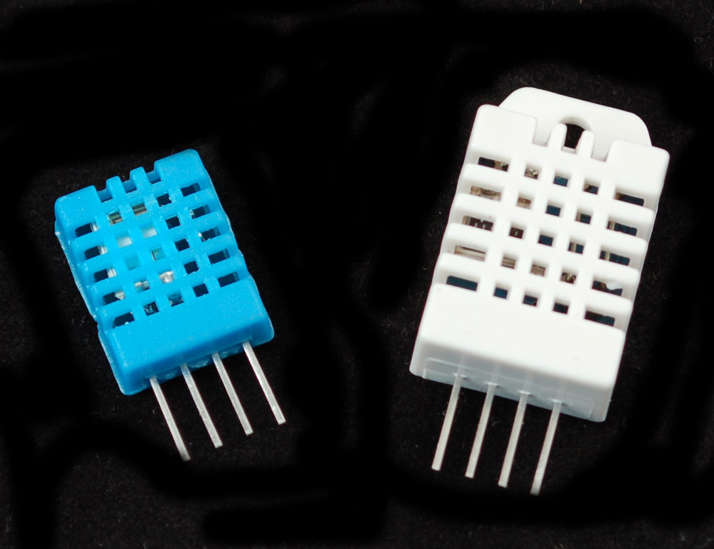
DHT11 vs DHT22
We have two versions of the DHT sensor, they look a bit similar and have the same pinout, but have different characteristics. Here are the specs:
- Ultra low cost
- 3 to 5V power and I/O
- 2.5mA max current use during conversion (while requesting data)
- Good for 20-80% humidity readings with 5% accuracy
- Good for 0-50°C temperature readings ±2°C accuracy
- No more than 1 Hz sampling rate (once every second)
- Body size 15.5mm x 12mm x 5.5mm
- 4 pins with 0.1" spacing
- Low cost
- 3 to 5V power and I/O
- 2.5mA max current use during conversion (while requesting data)
- Good for 0-100% humidity readings with 2-5% accuracy
- Good for -40 to 125°C temperature readings ±0.5°C accuracy
- No more than 0.5 Hz sampling rate (once every 2 seconds)
- Body size 15.1mm x 25mm x 7.7mm
- 4 pins with 0.1" spacing
As you can see, the DHT22 is a little more accurate and good over a slightly larger range. Both use a single digital pin and are 'sluggish' in that you can't query them more than once every second or two.
You can pick up both the DHT11 and DHT22 from the adafruit shop!
Connecting
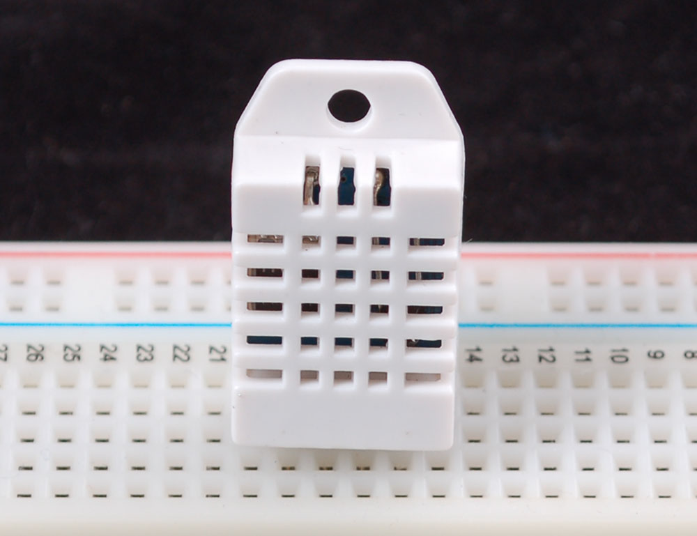
Luckily it is trivial to connect to these sensors, they have fairly long 0.1"-pitch pins so you can plug them into any breadboard, perfboard or similar.
Wiring
Likewise, it is fairly easy to connect up to the DHT sensors. They have four pins
- VCC (3 to 5V power)
- Data out
- Not connected
- Ground
Simply ignore pin 3, its not used. You will want to place a 10K resistor between VCC and the data pin, to act as a medium-strength pull up on the data line. The Arduino has built in pullups you can turn on but they're very weak, about 100K
This diagram shows how we will connect for the testing sketch. Connect data to pin 2, you can change it later to any pin.

Arduino library code
To test the sketch, we'll use an Arduino. You can use any micrcontroller that can do microsecond timing, but since its a little tricky to code it up, we suggest verifying the wiring and sensor work with an Arduino to start.
Begin by downloading the DHT library from our github repository. To download, click the DOWNLOADS button in the top right corner. Rename the uncompressed folder DHT and make sure that it contains the dht.cpp file and others. Then drag the DHT folder into the arduinosketchfolder/libraries/ folder. You may have to create that libraries sub-folder if it doesnt exist. Restart the IDE
Now load up the Examples→DHT→DHTtester sketch

If you're using a DHT11 sensor, comment out the line that sets the type:
//#define DHTTYPE DHT22 // DHT 22 (AM2302)
and uncomment the line that says
#define DHTTYPE DHT11 // DHT 11
This will make the data appear correctly for the correct sensor. Upload the sketch!

You should see the temperature and humidity. You can see changes by breathing onto the sensor (like you would to fog up a window) which should increase the humidity.
Downloads!
- DHT11 datasheet (in chinese, so see the DHT22 datasheet too!)
