This is an old revision of the document!
Table of Contents
Microtouch!
Microcontroller
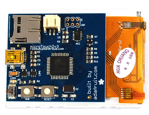
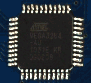
The brains of the Microtouch board is an Atmega32u4 in TQFP package. The nice thing about this chip is the built-in USB support and lots of pins.
Lithium Polymer batteries & charger
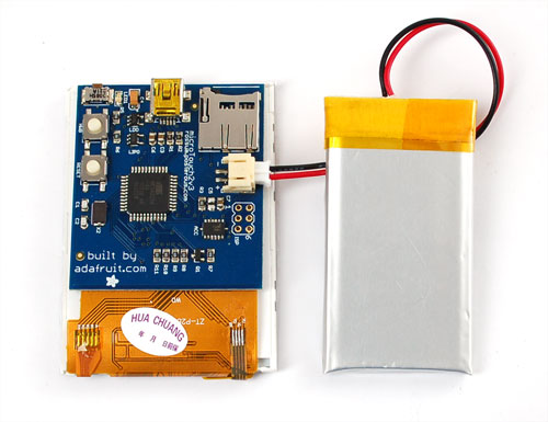
The board has a built in single-cell 3.7v LiPoly charger (MCP73812). The LiPoly should be connected to the 2-pin 2.0mm JST-PH - verify polarity before connecting! The charger chip is very simple but will properly charge the lipoly. The charge rate is set to be about 250 mA, so do not plug it into a non-powered hub. It should work fine with any computer. Unfortunately there is no notification when the battery is charging (say an LED) but you can detect the battery status via the microcontroller's ADC pin. You can change the charge rate by adjusting R17 from 4.7K. Check the MCP73812 datasheet for the resistor that corresponds to your desired charge rate
3.3V power supply
The output of the lithium polymer battery (or USB passthru) connects to a LP2985 3.3v LDO. This regulator is fairly good quality and will give about 1% precision output and up to 150mA. Most of the power usage in this design is for the 4 x backlight LEDs which can be up to 50mA total. There is also 10-20 mA taken by the microcontroller, ~20mA taken by the TFT, and another 2 mA for the red indicator LED. The accelerometer takes almost no power.
Indicator LED
This LED is on pin PC7 and is used to indicate when the bootloader is active. You can use it for pretty much anything you'd like
Crystal
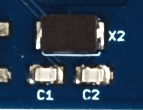
The timing crystal is at 16 MHz. This is overclocking the Atmel a bit (at 3.3v it would prefer to be at 12MHz) - we test the chips to verify they work before shipment. The reason for overclocking is to be able to do fast video-speed display interfacing. The crystal has two stability capacitors next to it.
Power button (aka How to turn it on!)
The Microtouch uses a trick that allows it to turn itself off when battery powered. The LDO has an Enable pin that is pulled to ground (that is, the LDO is disabled by default). When the right-angle power button is pressed, this enables the LDO which turns on the AVR. The first thing the AVR does is pull the Enable pin high (its connected to PF0). When the button is let go, the pin will keep the LDO activated. This means that if you want to write your own code for the Microtouch to make sure the first thing that happens is setting PF0 to an output and pulling it high.
Of course, to turn itself off, the chip can drop PF0 low. The user will have to press the button again to turn it back on. This shoudln't be done when on USB power because the bootloader can get stuck in a 'brownout loop' but a press of the reset button will 'kick' it out.
Reset Button
The Reset button is connected to the AVR's reset pin. Pressing it will turn off the system as it causes the enable pin to drop low.
HWB Button
The HWB is the HardWare Bootloader button. To enter the bootloader you'll need to press both the Power and HWB button and then press and release the reset button at the same time you have the Power and HWB buttons pressed.
ISP header & AVR reprogramming
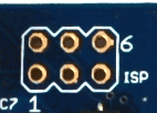
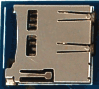
The AVR can be reprogrammed by any standard AVR programmer and avrdude or similar. While programming, be sure to remove the microSD card as it will interfere with programming and could end up bricking the microcontroller! If reprogramming, don't forget you have to keep the power button pressed during the programming cycle. If you're doing a lot of development you will probably want to either provide power to the target by using a programming board that can power VCC with 3.3V or solder a wire between both sides of the power button. Just make sure that the target power really is 3.3v, for example the USBtinyISP provides 5 not 3.3v which could damage the LCD
LCD backlight
The LCD has 4 backlight white LEDs in parallel. We use a 47 ohm resistors (the image shows 68, that's a prototype) on each Cathode (K) and drive the cathode with a NPN connected to pin PC6. You can dim the backlight by software-PWMing the pin (there is no hardware PWM on that pin). For the most part either the backlight is on or off. When off, the display is not visible.

